9
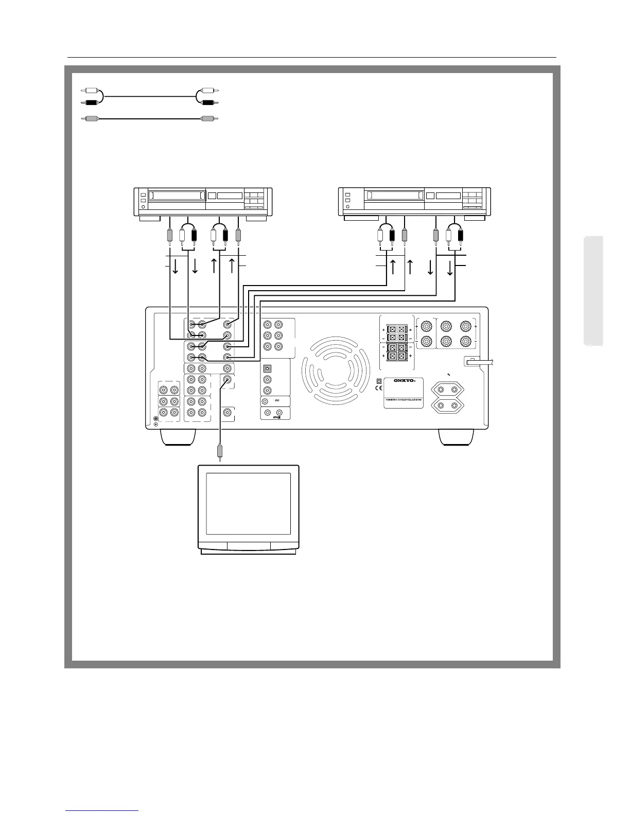
Video equipment connections
R
V
L
OUT
IN
VIDEO-1
OUT
IN
VIDEO-2
OUT
IN
OUT
IN
IN
IN
TAPE-1
TAPE-2
DVD
R
L
PHONO
CD
GND
R
L
R
L
R
L
R
L
FRONT
SPEAKERS
MAIN
CENTER
SPEAKER
SURROUND SPEAKERS
V
OUT
(REC)
IN
(PLAY)
OUT
(REC)
IN
(PLAY)
MONITOR
OUTPUT
SUBWOOFER
PRE OUT
FRONT REMOTE SPEAKERS
R
L
TUNER
FRONT
DIGITAL INPUT
DIGITAL 1
(OPTICAL)
DIGITAL 2
(COAXIAL)
OUT
IN
REMOTE CONTROL
SURROUND
CENTER SUBWOOFER
DIGITAL 3
(COAXIAL)
MULTI
CHANNEL
INPUT
L
R
R
L
CAUTION: SPEAKER IMPEDANCE
6 OHMS MIN. / SPEAKER
MODEL NO.
A-DS650
AC OUTLETS
SWITCHED
TOTAL 100W MAX.
50Hz
AC230V
Monitor TV
VIDEO IN
Video Cassette Recorder
(VIDEO-1)
Video Cassette Recorder
(VIDEO-2)
AUDIO IN
VIDEO IN
AUDIO OUT
AUDIO OUT
VIDEO OUT
VIDEO OUT
AUDIO IN
VIDEO IN
•
On each pair of connectors, the connector (marked R, red) corresponds to the
right channel, and the connector (marked L, white) to the left channel.
•
The yellow connector (marked V) is used for video connection.
•
Please refer to the instruction manual for each component when you make any
connections.
•
This unit can be used only with a monitor TV equipped with a video input.
• Interference may be created between the TV and this unit. If this interference occurs, place the unit and the TV as far apart as pos-
sible.
•
When using a playback-only VCR, connect its output to the A-DS650’s video input connector.
 Loading...