73
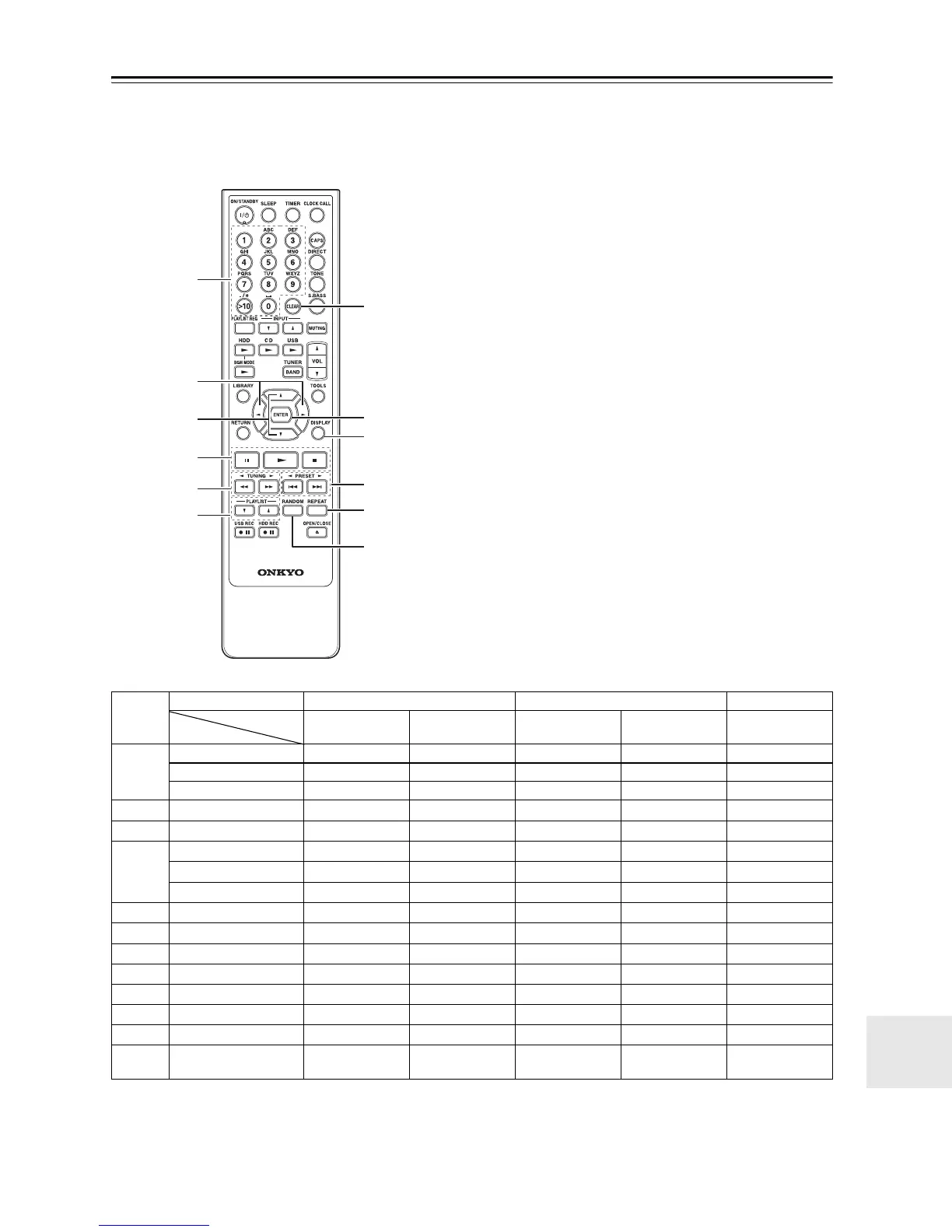
Controlling External Components
Explanation of buttons for using the Onkyo MD recorder, cassette deck, CD recorder, or RI Dock, when con-
nected to the MD/TAPE jack, DOCK/CDR jack or DIGITAL IN jack of the CD/HDD receiver.
• See page 19 for instructions on connecting the components.
• To control the MD recorder, the Input Display for the MD/TAPE jacks must be set to “MD” (see page 45).
Example: Shows the case of l:
the [RANDOM] button.
• When the cassette deck is connected to the MD/TAPE
jack of the CD/HDD receiver and the input source is
set to “TAPE”, it works as a DOLBY NR button.
• When the CD recorder is connected to the DOCK/
CDR IN/OUT jack of the CD/HDD receiver and the
input source is set to “DOCK”, it works as a SHUF-
FLE button. However, the input source is set to “CD-
R”, it works as a RANDOM button. In the same way,
when the CD recorder is connected to the OPTICAL
DIGITAL IN jack and the input source is set to “CD-
R/dig”, it works as a RANDOM button.
See the instruction manual for each connected component for details. For column items with no notation, buttons will
not function when pressed.
6
4
1
2
5
3
7
9
8
bk
bl
bm
Jack MD/TAPE DOCK/CDR DIGITAL IN
TAPE MD DOCK CD-R CD-R/dig
a
1 ~ 9 1 ~ 9 1 ~ 9 1 ~ 9
0 10/0 10/0 10/0
>10 >10 >10 >10
b
e/r ALBUM q/w
c
q/w CURSOR q/w
d
111111
2 22222
3 t3333
e
5/45/45/45/45/4
f
PLAYLIST q/w PLAYLIST q/w
g
CLEAR CLEAR CLEAR
h
ENTER ENTER SELECT ENTER ENTER
i
DISPLAY DISPLAY BACKLIGHT DISPLAY DISPLAY
j
7/65/47/67/67/67/6
k
REPEAT REV MODE REPEAT REPEAT REPEAT REPEAT
l
RANDOM DOLBY NR
RANDOM
(PLAY MODE)
SHUFFLE* RANDOM RANDOM
Button
Input source
 Loading...