Do you have a question about the Onkyo HT-RC660(B) and is the answer not in the manual?
Critical components identified by a mark require special attention for risk of fire and electric shock.
Step-by-step instructions to enter the audio debug mode for analyzing sound troubles.
Lists codes for source formats, DSP decode, and HDMI audio lock for debug analysis.
Details on input channels, listening mode transitions, and channel information for FL display.
Information on audio output status (OK/NG) and detailed input format parameters.
Data related to DA830 input signals and sequence numbers for DIR and DAC.
Procedure to activate HDMI debug mode for checking HDMI-related operations.
Explains how input and output resolutions are displayed in HDMI debug mode.
Details on how 4K upscaling and 3D display signals are processed and shown in debug mode.
Information on identifying resolution errors and the status of EDID reads.
Displays HDMI input mode, color depth, and various 3D format details for signal checks.
Information on PC resolution signals and details of HDMI output for troubleshooting.
System for analyzing unit status, especially when in Protect mode or powered off.
A list of codes corresponding to different listening modes for service information display.
Procedures for entering test modes and confirming the firmware version.
Method to confirm output voltage and thermal sensor readings for operational checks.
Verifies model name, destination settings, and general test mode operations.
Details idling timer functions and Wi-Fi connection checks as part of operation verification.
Tests voltage-detection protectors and verifies the update route for firmware.
Confirms Wi-Fi connectivity and checks the Zone2 DAC audio output path.
Verifies 12V trigger output, current detection protectors, and output sensor functionality.
Confirms key operations, network connectivity, and cooling fan performance.
Verifies front panel display, LEDs, headphone operation, and FM radio functionality.
Confirms RDS, OSD, CEC operations, and Dolby test tone output for each channel.
Checks video signal detection and verifies video signal flow through input and output paths.
Verifies the proper lighting and display of all segments on the front panel FL display.
Detailed table outlining various test operations (1-00 to 1-09) for checking unit functions.
Continuation of the detailed test operations table, covering various functional checks.
Procedures for entering and performing tests related to video, HDMI, and audio signal processing.
Details on checking the cooling fan's operation and verifying thermal sensor and VOLH voltage.
Step-by-step instructions for adjusting idling current, including pre-adjustment, aging, and final adjustment.
Identifies specific terminals and connection points for performing the idling current adjustment.
Important notice regarding the confidential nature of firmware update information.
Steps required before starting the firmware update, including USB device preparation and file download.
Detailed procedure for performing the firmware update via USB, including overwriting existing versions.
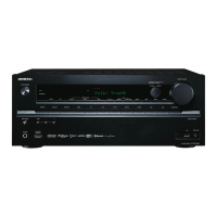
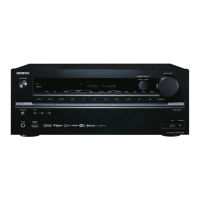
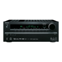
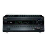
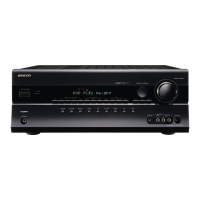
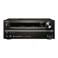
Provides a visual breakdown of the AV receiver's main components and their physical locations.
Illustrates the overall signal flow and interconnections of audio processing circuits.
Shows the block-level diagram of the video signal processing and routing within the receiver.
Details the interconnected digital audio processing blocks, including DACs and ADSPs.
Provides the detailed schematic for the Audio Signal Processing (ASP) section of the unit.
Shows the detailed circuitry of the audio amplifier stage, including power output and protection.
Detailed schematic for the Class-A amplifier stages, illustrating biasing and output circuitry.
Provides the schematic for the Digital-to-Analog Converter (DAC) filter circuits, crucial for audio output quality.
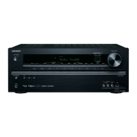
Details the physical connection points for various terminals, including video and speaker outputs.
Shows the schematic for the front panel display (FL tube) and associated driver circuits.
Details the circuitry for the front panel display, indicator LEDs, and headphone jack.
Schematic illustrating the primary power supply circuits, including transformers and filtering.
Shows the detailed schematic of the main microprocessor and its peripheral connections.
Details the schematic for the Virtual Machine Processing Unit (VMPU) and related power supply circuits.
Illustrates the schematic for HDMI signal processing, including input receivers and output transmitters.
Details the specific circuitry for handling incoming HDMI signals and their decoding.
Shows the schematic for the Video Signal Processor (VSP) responsible for video scaling and enhancement.
Details the schematic of the Digital Signal Processor (DSP), Digital Interface Receiver (DIR), and DAC circuits.
Provides the schematic for the DSP memory interface and related components.
Details the schematic for network interfaces, USB ports, and power supply control for these functions.
Shows the schematic related to the second Digital Signal Processor's memory interface.
Provides the schematic for the DSP memory interface, detailing connections and components.
Illustrates the schematic for HDMI signal reception, processing, and output.
Shows the schematic specific to the front panel HDMI input connector and associated circuitry.
Details the schematic for Wi-Fi, Bluetooth module, and the FM tuner section.
Lists semiconductor components like transistors and diodes used in the unit's construction.
Lists structural hardware like screws, cushions, badges, labels, and cabinet parts.
Details transformer coils, switches, connectors, and flexible flat cables used in the unit.
Lists included accessories such as remote controls, batteries, microphones, and cables.
Lists materials used for packaging the unit, including pads, bags, tape, cartons, and UPC labels.
Lists accessories provided with the unit, such as remote controls, batteries, and various instruction manuals.
Lists semiconductor components for PC Board U001, including diodes and transistors.
Lists resistor components for PC Board U001, detailing their values and part numbers.
Lists semiconductor components for PC Board U003, including diodes and transistors.
Details the trans coils used on PC Board U003, specifying their types and part numbers.
Lists capacitor components for PC Board U003, including their types and part numbers.
Continues the list of capacitor components for PC Board U003, detailing types and part numbers.
Lists resistor components for PC Board U003, specifying their values and part numbers.
Lists resistor components for PC Board U005, specifying their values and part numbers.
Lists semiconductor components for PC Board U002, including transistors and hybrid ICs.
Lists resistor components for PC Board U002, detailing their values and part numbers.
Lists the switch terminal components for PC Board U002, including part numbers.
Lists semiconductor components for PC Board U008, including diodes and transistors.
Lists semiconductor components for PC Board U009, including transistors and diodes.
Details the trans coils used on PC Board U009, specifying their types and part numbers.
Lists capacitor components for PC Board U009, including their types and part numbers.
Lists semiconductor components for PC Board U010, including diodes and hybrid ICs.
Lists capacitor components for PC Board U010, including their types and part numbers.
Lists semiconductor components for PC Board U012, including transistors and hybrid ICs.
Lists capacitor components for PC Board U012, including their types and part numbers.
Lists resistor components for PC Board U012, specifying their values and part numbers.
Lists the switch terminal components for PC Board U012, including part numbers.