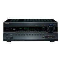
Do you have a question about the Onkyo HT-RC630 and is the answer not in the manual?
Steps to enter AUDIO DEBUG MODE-1 for audio troubleshooting.
Defines input channel formats for listening mode transitions.
Displays HDMI resolution information on FL screen.
Shows input resolution details for PC signals.
Lists codes for various listening modes.
Explains button press notations for test modes.
Verifies unit model and destination settings.
Checks voltage detection for protection circuits.
Tests selector muting time reduction functionality.
Procedure for adjusting idling current for optimal performance.
Instructions for updating firmware via USB.
Visual breakdown of the unit's main components.
First part of the system block diagram.
Schematic for Digital/Video section, Part 6.
| Output level | 100 mV |
|---|---|
| Receiver type | Surround |
| Frequency range | 5 - 100000 Hz |
| Input sensitivity | 200 mV |
| Audio output channels | 5.1 channels |
| Signal-to-Noise Ratio (SNR) | 100 dB |
| Dynamic power per channel (3 Ohm) | 160 W |
| Dynamic power per channel (4 Ohm) | 125 W |
| Dynamic power per channel (8 Ohm) | 85 W |
| Power output per channel (1KHz@6 Ohm) | 120 W |
| Power output per channel (20-20KHz@8 Ohm) | - W |
| HDMI in | 6 |
| Audio (L/R) in | 7 |
| Composite video in | 4 |
| Digital audio coaxial in | 2 |
| Component video (YPbPr/YCbCr) in | 1 |
| Speakers connectivity type | - |
| Bluetooth | Yes |
| Ethernet LAN | No |
| Bluetooth version | 2.1+EDR |
| Bluetooth profiles | A2DP, AVRCP |
| AM band range | 522 - 1710 kHz |
| FM band range | 87.5 - 108 MHz |
| Supported radio bands | AM, FM |
| Preset stations quantity | 40 |
| Product color | Black |
| Audio decoders | Dolby TrueHD, DTS-HD Master Audio |
| Damping factor | 60 |
| Apple docking compatibility | Not supported |
| AC input voltage | 230 V |
| AC input frequency | 50 Hz |
| Power consumption (standby) | 0.3 W |
| Power consumption (typical) | 330 W |
| Package weight | 10500 g |
| Depth | 321 mm |
|---|---|
| Width | 435 mm |
| Height | 150 mm |
| Weight | 8100 g |