HT-R960
SCHEMATIC DIAGRAMS-11
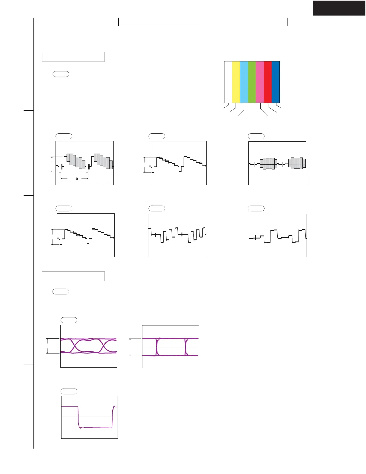
WAVEFORM SECTION-2/3
(SD-4 : B4)
<Notes>
1. WF21 is short for Waveform-21 .
2. Refer to SD-4 (SCHEMATIC DIAGRAMS-4) for the location
of each waveform on circuit.
3. SD-x : XY is short for Schematic Diagrams-x and each
socket's location, X=A to H, Y=1 to 5.
4. In the case that video outputs are not connected to video devices,
video signal output levels are doubled.
Video Waveform Part
WF21
WF24
WF22
WF25 WF21
WF23
HDMI Waveform Part
Video source color and pattern
White
Yellow
Cyan
Green
Magenta
Red
Blue
Composite waveform S-Video Y waveform
Component Y waveform Component PB waveform Component PR waveform
S-Video C waveform
720 mVp-p 728 mVp-p
1.2 Vp-p (H)
1V
(NTSC)
1.0 Vp-p
1V
1.0 Vp-p
1V
280 mVp-p
HDMI D0,D1,D2 waveform
HDMI CK waveform
2,227.5MHz
(1080p,12bit)
222,75MHz
(1080p,12bit)
27MHz
(480i, 8bit)
SD-8 : B5
D0,D1,D2 Eye-pattern waveform, frequency and level vary
according to video resolution, aspect and profile.
Waveforms above are examples.
CK waveform, frequency and level differ according to video resolution, aspect and profile.
D0,D1,D2 are just CK x10.
SD-8 : B5
600mV
360mV
(SD-4 : B4) (SD-4 : B4)
(SD-4 : B2) (SD-4 : B2) (SD-4 : B2)
<Notes>
1. WF41 is short for Waveform-41 .
2. Refer to SD-8 (SCHEMATIC DIAGRAMS-8) for the location of each waveform on circuit.
3. SD-x : XY is short for Schematic Diagrams-x and each socket's location, X=A to H, Y=1 to 5.
6.36 s
WF42
WF41
A
1
2
3
4
5
BCD

 Loading...