EasyManua.ls Logo

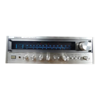
Onkyo TX-1500 - Service Procedures; Component Removal Procedures; Component Replacement Procedures; Stringing Diagram

Onkyo TX-1500
11 pages
To Next Page IconTo Next Page
To Previous Page IconTo Previous Page
Loading...
SERVICE
PROCEDURES
:
I.
REMOVEMENT
OF
DIAL
GLASS
(1)
Pull
TUNING
knob
off
the
TUNING
shaft.
(2)
Remove
four
hex
volts.
2.
REMOVEMENT
OF
FRONT
PANEL
(1)
Pull
all
knobs
off
control
shafts.
(2)
Remove
two
hex
volts.
(2)
Remove
three
screws.
3.
REPLACING
STEREO
/
LOCKED
INDICATOR
(L.E.D.)
(1)
Remove
four
screws
which
hold
the
top
cover
to
the
chassis
and
lift
off the
top
cover.
(2)
Remove
a
screw
which
hold
the
PC
board
to
the
front
bracket.
(3)
There
is
a
cathode
mark
on
the
foot
of
L.E.D.
4.
REPLACING
DIAL
LAMP
fig—3
(1)
Remove
four
screws
which
hold
the
top
cover
to
the
chassis
and
lift
off
the
top
cover.
(2)
Remove
the
two
screws
which
hold
the
lamp
case
to
the
front
bracket.
5.
REPLACING
POWER
FUSE
(U.S.A.
MODEL)
(1)
Remove
four
screws
which
hold
the
top
cover
to
the
chassis
and
lift
off
the
top
cover.
Cathode
aie
mark
(2)
Replace
a
fuse
between
a
back
panel
and
a
power
transformer.
6.
REPLACING
SPEAKER
FUSE
(1)
Remove
a
screw
which
hold
the
fuse
cover
to
the
back
panel.
STRINGING
DIAGRAM
2
1.
Open
the
variable
capacitor
complete
and
tie
dial
cord
=Ste
to
the
spring
of
the
drum.
2.
Thread
dial
cord
in
the
direction
of
arrow
from
(to
(8)
and
wind
dial
cord
three
turns
around
the
tuning
shaft
counter-clockwise.
3.
Thread
dial
cord
in
the
direction
of
arrow
from
G)to
45.
;
oY
q0.
ate
2
co
F
seas
|
:
1
Sean?”
Frequency......Max.
4.
Thread
dial
cord
to
the
dial
pulley
5.
©}
Dial
Pulley
2

Related product manuals