4 - Power Management
4.1 - Wake-Up Events
The Helix platform supports multiple power states. The wake-up events can be configured in the
BIOS. This section describes the supported power management functions and gives information on
protection circuitry for power adapters. Low power shutdown is an additional option in the BIOS. See
Appendix C for more information.
Low Power
shutdown, S5, S3
4.2 - Protection Circuitry
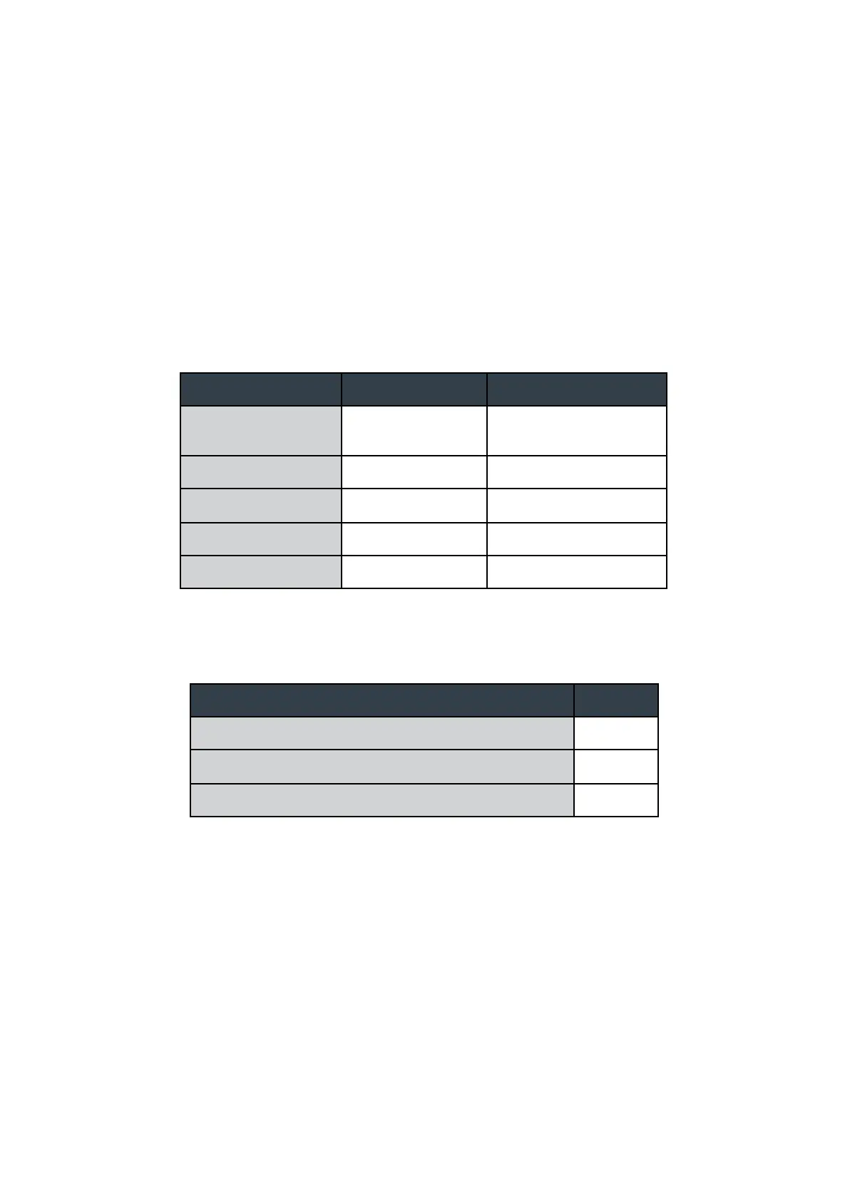
Nominal operating voltage (Rated DC value of input)
Undervoltage protection trip DC level (system turns off)
Maximum safe DC voltage (system not damaged)
These DC levels specified are the absolute max values for the pins for function and safety of the
system. The protection circuitry allows for brief transient voltages above these levels without the
system turning off or being damaged. A transient voltage suppressor on the power input allows
momentary excursions above stated limits. For input power consumption and current see
Appendix A.