Do you have a question about the Onlogic HX310 and is the answer not in the manual?
Explains system power states and wake-up triggers.
Details voltage protection levels for system stability.
Lists regulatory compliance standards for the device.
Presents power consumption data for various system configurations.
Offers detailed information on BIOS screens and settings.
Lists pin configurations for M.2 and mPCle expansion ports.
Covers safe installation, handling, and environmental precautions.
Introduces the Helix 300 series, its features, and intended use.
Lists the standard accessories included with the system.
Covers physical dimensions, CPU options, and memory configurations.
Details I/O ports, expansion slots, and onboard headers.
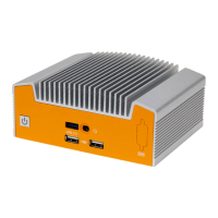
Illustrates and describes the front panel I/O ports of the HX310.
Illustrates and describes the back panel I/O ports, including dual LAN option.
Details the I/O ports on the front panel of the Helix system.
Explains the function and status indication of the power button and LED.
Describes the 3FF SIM card slot for LTE module support.
Details the COM DB9 port and its RS-232, RS-422, RS-485 configurations.
Explains the CAN port functionality and pinout for CAN2.0 A/B.
Details the USB 3.2 Gen 2 and USB 2.0 ports on the front panel.
Describes the optional DIO card and dual LAN feature.
Details the specifications and pinout of the barrel jack power input.
Describes DisplayPorts and the functionality of LAN ports with LED indicators.
Details the dual stack USB 3.2 ports on the rear panel.
Explains the terminal block power option, its specifications, and pinout.
Describes the M.2 B-Key slot and its supported form factors and interfaces.
Describes the M.2 E-Key and M.2 M-Key slots for expansion.
Details the specifications of the two onboard DDR4 SO-DIMM slots.
Details the onboard COM headers and their serial port configurations.
Covers CAN header, BIOS updates, and power switch header functionality.
Details jumpers for clearing CMOS and selecting power modes.
Provides pinout and function for the ATX/CMOS jumper header.
Explains the RTC battery use and the TPM header for security.
Details the fan header for powering and controlling fans.
Describes the onboard USB 2.0 header and its pin configuration.
Explains the HDMI-CEC expansion header.
Details the 4-pin JST and 2-pin headers for power input and output.
Provides step-by-step instructions for wall and DIN rail mounting.
Shows dimensional drawings related to wall and DIN rail mounting.
Illustrates the system mounted on a DIN rail with dimensions.
Provides instructions, screw specs, and dimensional drawings for VESA mounting.
Explains system power states and configurable wake-up events.
Details voltage protection levels for system stability.
Lists regulatory compliance standards for the device.
Presents power consumption data for various system configurations.
Details memory configurations and LAN controller specifications.
Shows power consumption for the low and mid HX310 configurations.
Provides guidance on the Isolated Digital I/O feature.
Offers detailed information on BIOS screens and settings.
Details usage of the on-board CAN transceiver.
Details thermal test results at 50C ambient temperature.
Details thermal test results at 0C ambient temperature.
Provides the pin configuration for the M.2 B-Key slot.
Provides the pin configuration for the M.2 E-Key slot.
Provides the pin configuration for the M.2 M-Key slot.
Provides the pin configuration for the mPCle slot.
Covers essential safety precautions for device installation and handling.
Provides safety guidance and installation precautions in French.
Describes an issue where the system may power on after an interruption.
| Brand | Onlogic |
|---|---|
| Model | HX310 |
| Category | Industrial PC |
| Language | English |