18
BLUE
BLACK
BLACK
+
LED
Buzzer
R = 1kΩ
-
Relay
BLUE
BLACK
BLACK
+
Diode
1N4007
-
Fig. 2
GREEN/
BLACK
M.S.
BROWN
+V
-V
-IN
+IN
C
N.C
N.A
BROWN
Item 05259
BLACK
BLACK
+
-
Fig. 4
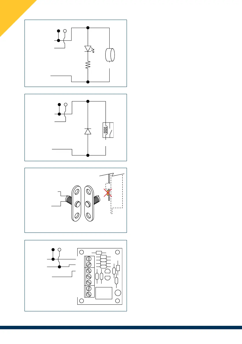
Fig.1: Connection of the Alarm /
Failure output directly to low-power
loads, such as LEDs or Buzzers.
Do not connect to loads
greater than 50 mA directly.
(Item 246 - 248 only).
Fig.2: Connection of the Alarm /
Failure output to an interface relay in
order to signal the alarm status by
devices with larger loads
(e.g. 230V-powered alarm devices).
(Item 246 - 248 only).
Fig.3: Connection to an alternative
magnetic sensor (M.S.)
Remove the built-in magnet,
installed on the back of the
striking plate.
Fig.4: Remote signalling of door
status using our interface circuit
item 05259.
Do not connect the brown wire
to a direct relay, risk of damage
to the magnetic sensor.
Fig. 1
Fig. 3