21
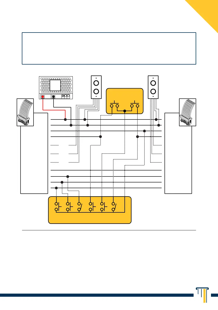
BASIC INTERLOCKING DIAGRAM
¹ GREEN BAND contacts are to be used only if a deadbolt status signalling is required
(by means of optional indicator lamp, e.g. item 55010 or item 55030).
² the HOLD OPEN contact (optional) is to be used only if continuous unlocking of the
deadbolt is required for prolonged periods (e.g. Timer or Key Switch).
³ Desk Control Console, individual push-buttons on the doors or N parallel control
devices of a different kind can be installed to open the doors.
4
Only on item 246 - 248.
In order to use the interlock feature (linking the opening of one lock to the
closing of another) simply connect Ground (GND, Green/Black) and
Interlock contacts (Yellow/Black) to each other of the N installed locks.
BLACK BLACK
GREEN/BLACK GREEN/BLACK
BLACK BLACK
YELLOW YELLOW
GREEN GREEN
ORANGE ORANGE
E R LK D1
D2 A/M
BROWN
GREEN BAND
¹
BROWN
GREEN BAND
¹
ORANGE
GREEN BAND
¹
ORANGE
GREEN BAND
¹
RED
GREEN BAND
¹
RED
GREEN BAND
¹
RED/BLACK RED/BLACK
YELLOW/BLACK YELLOW/BLACK
POWER SUPPLY
DOOR 1 DOOR 2
N.O. DOOR MOUNTED
PUSH-BUTTONS³
(OPTIONAL)
DESK CONTROL CONSOLE³
(OPTIONAL, INSTALLER’S RESPONSIBILITY)
E EMERGENCY RELEASE
4
R RESET
4
LK LOCKOUT (BUTTON DISABLING)
4
D1 UNLOCK DOOR 1
D2 UNLOCK DOOR 2
A/M AUTOMATIC / MANUAL
(BUTTON ENABLING)
(N.C.)
(N.O.)
(COM)
INDICATOR LAMP
ITEM 55010
(OPTIONAL)
INDICATOR LAMP
ITEM 55010
(OPTIONAL)
12/24V
3A DC
+V -V
N
L