NLV-5201 Specifications Manual
Light paths of the imager scanner, LED illumination, and aiming. Make
sure that the lens is free from dust and dirt before scanning. For more
information, see “Cleaning the NLV-5201” on page 37.
Screw holes (two on the bottom and two on the side) that you can use to
mount the imager scanner. 2 holes on the bottom and side. For the
mounting hole dimensions, see “Mechanical Drawing” on page 41.
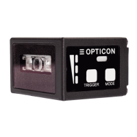
Use the control panel to run Test mode, Tune mode, and Aim mode. You
can also select the bank. For more information, see “Control Panel
Operation Specifications” on page 7.
Sound from a built-in buzzer comes out through these holes. When the
holes are covered, the buzzer sound is diminished. The sound varies
depending on the settings. You can configure the frequency, loudness,
and duration of the buzzer.
Indicates status with 3-color LEDs: red, orange, and green. For more
information, see “LED Indicator Specifications” on page 8.
The default key is the trigger key. When you select a mode from the
control panel, the trigger key operates as an execution key.
Use the mode key to select and cancel the mode. Press and hold the
mode key to return to saved settings bank select mode.
5 Basic Operation Mode
Make sure you understand the symbols used to indicate the states of the status LED indicator.
 Loading...