RS232 SERIAL OUTPUT FORMAT
Follow the pin out of Table 5 below to connect the indicator the RS-232 Serial device
Table 5. DB9 Pin Description
DB9 Pin Definition Function
2 TXT Transmit Data
3 RXD Receive Data
5 GND Ground Interface
The serial output format depends on the settings for parameter C18. The serial output consists
of a string of ASCII characters. Here is a list of the serial parameters
8 data bits
1 stop bits
No parity
No handshaking
2. RS-232 Connection (DB 9 9 pin Connector)
Table 4. Wiring Color Code
Signal Name Description
+Exe/ +EX Positive excitation voltage to load cell
+IN / +SIG Positive output signal from load cell
HD / SHLD Shield Wire
-IN / -SIG Negative output signal from load cell
-EXC / -EX
Color Code
RED
GREEN
YELLOW/THICK BLACK
WHITE
BLACK Negative excitation voltage to load cell
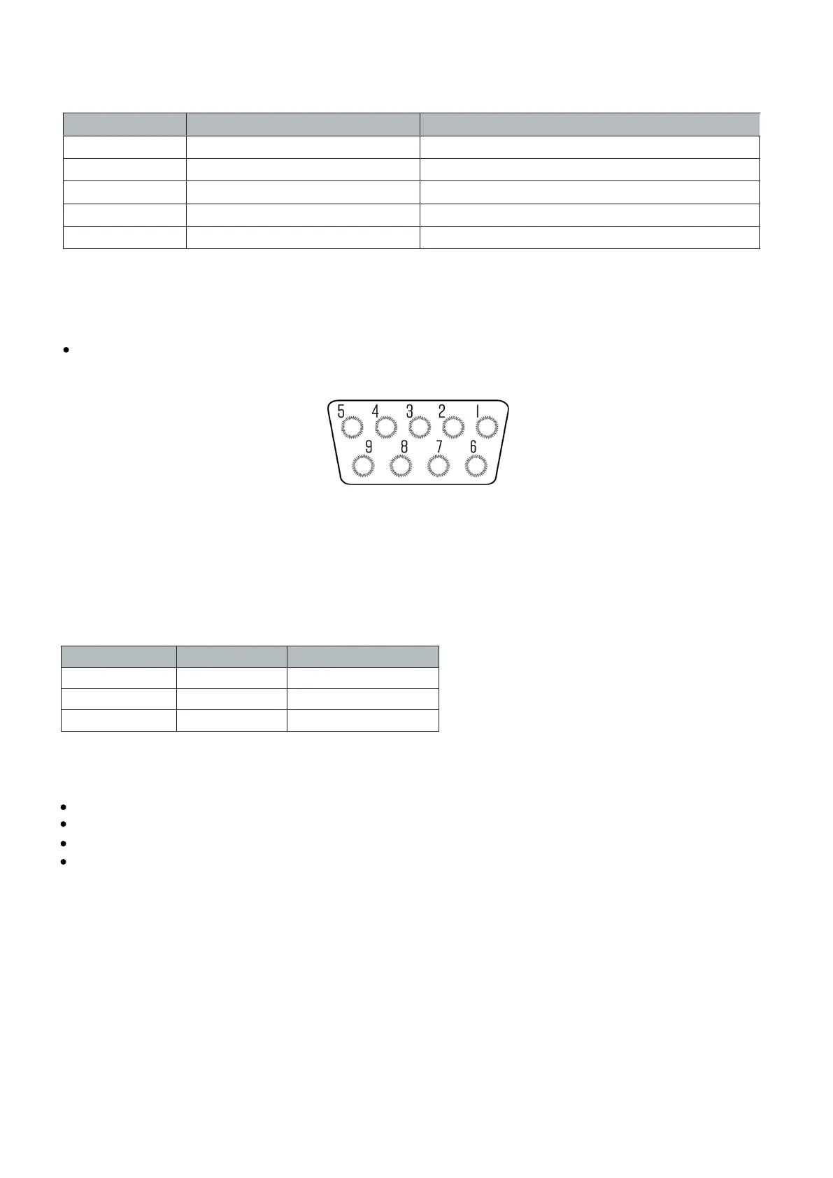
The DB9 9 pin serial connector is used for different purposes depending on the indicator model
Figure 4 shows the pin assignment on the DB9 9 pin connector
FIGURE 4: DB9 SERIAL CONNECTOR PINOUT
- 16 -