OPTIMOD-AM DIGITAL INSTALLATION
2-31
Adjustment of the high frequency transmitter equalizer controls cannot be done
into a dummy load because the transmitter will overshoot and ring differently
when loaded by the reactance of your antenna system.
F) Set the HF
DELAY and HF GAIN controls to OFF.
If no overshoot is observed, skip to step (H).
G) Adjust the HF
FREQ and HF DELAY controls to minimize ringing and overshoot.
The HF
FREQ and HF GAIN controls interact. First, adjust the HF FREQ con-
trol until any ringing is reduced to the same level as the flat part of the
square wave (you will still have ringing, but no overshoot). Then adjust
the HF
DELAY control (which will further reduce the amplitude of the
ringing on the leading edge of the square wave while introducing a new
ring on the trailing edge) until the amplitudes of the ringing at the lead-
ing and trailing edges are equal. The peaks of the ringing at both edges
should approach the flattop modulation level as closely as possible with-
out exceeding it. Note that the HF
GAIN control does most of the work.
Note also that the HF
DELAY control will produce little or no visible effect
until you set it beyond 40.
Adjusting the HF
DELAY control like this usually reduces the level of the
ringing to below the flattop modulation level. Reducing the setting of
the HF
FREQ control until the ringing is again at the flattop modulation
level will unbalance the ringing at the leading and trailing edge of the
square wave, and necessitate further adjustment of the HF DELAY con-
trol. Alternate between these two interactive controls until the peaks of
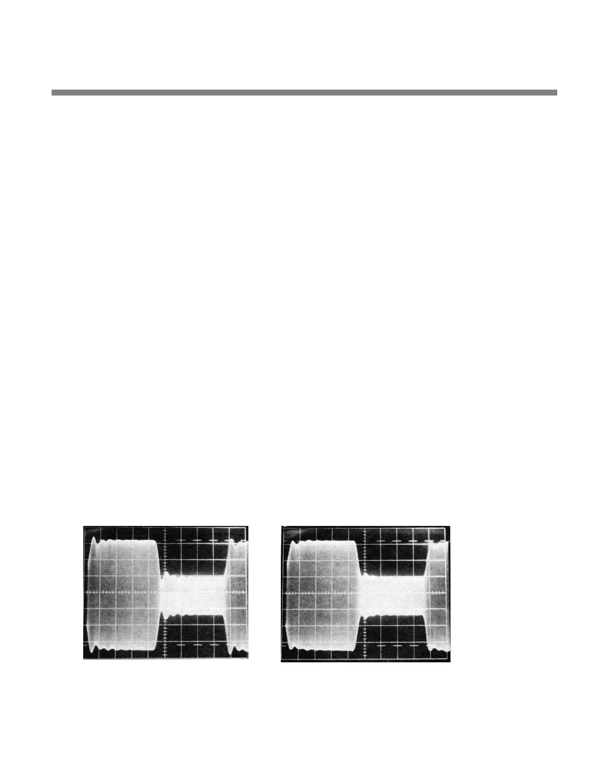
ringing at both the leading and trailing edges of the square wave are at
the flattop modulation level. Figure 2-10 illustrates a
typical waveform
before adjustment and Figure 2-11 shows the result of a successful ad-
justment. The waveform produced by your system may look quite differ-
ent.
H) Turn
off the square wave generator and turn off the carrier to allow the
transmitter to cool down for several minutes:
Figure 2-10: Unequalized RF envelope
(showing ringing)
Figure 2-11: RF envelope showing
successful HF equalization
 Loading...