Table of Contents
Index.........................................................................................................................0-8
Section 1 Introduction
.........................................................................................................................................1-1
ABOUT THIS MANUAL.......................................................................................................1-1
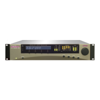
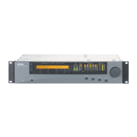
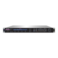
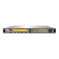
THE OPTIMOD-AM 9300 DIGITAL AUDIO PROCESSOR ......................................................1-1
Making the Most of the AM Channel....................................................................1-2
Controllable and Adjustable...................................................................................1-2
Versatile Installation................................................................................................1-3
PRESETS IN OPTIMOD-AM..............................................................................................1-4
Factory Presets .........................................................................................................1-5
User Presets..............................................................................................................1-5
INPUT/OUTPUT CONFIGURATION ........................................................................................1-5
Digital AES3 Input/Output......................................................................................1-5
Analog Input/Outputs .............................................................................................1-6
Remote Control Interface .......................................................................................1-6
Computer Interface .................................................................................................1-7
RS-232 Serial Port ............................................................................................................. 1-7
RJ45 Ethernet Connector ................................................................................................. 1-7
LOCATION OF OPTIMOD-AM..........................................................................................1-7
Optimal Control of Peak Modulation Levels.........................................................1-7
Best Location for OPTIMOD-AM ............................................................................1-8
If the transmitter is not accessible:.................................................................................. 1-8
If the transmitter is accessible: ........................................................................................ 1-9
STUDIO-TRANSMITTER LINK...............................................................................................1-9
Transmission from Studio to Transmitter...............................................................1-9
Digital Links .................................................................................................................... 1-10
Analog Microwave STLs ................................................................................................. 1-11
Analog Landline (PTT/Post Office Line)......................................................................... 1-12
AM Transmitters and Antennas............................................................................1-12
Bypassing the Transmitter's Internal Filters and Clippers...................................1-12
Power Supplies ......................................................................................................1-13
Pre-1965 Transmitters............................................................................................1-14
Asymmetry .............................................................................................................1-15
System Presets and Transmitter Equalization......................................................1-15
Antenna System.....................................................................................................1-17
USING LOSSY DATA REDUCTION IN THE STUDIO..................................................................1-17
ABOUT TRANSMISSION LEVELS AND METERING ..................................................................1-18
Meters ....................................................................................................................1-18
Figure 1-1: Absolute Peak Level, VU and PPM Reading ............................................... 1-19
Studio Line-up Levels and Headroom ..................................................................1-19
Transmission Levels................................................................................................1-20
LINE-UP FACILITIES .........................................................................................................1-20
Metering of Levels.................................................................................................1-20
Built-in Calibrated Line-up Tones.................................................................................. 1-20
Built-in Calibrated Bypass Test Mode............................................................................ 1-20
MONITORING.................................................................................................................1-21
Modulation Monitors and Their RF Amplifiers ...................................................1-21
Monitoring on Loudspeakers and Headphones..................................................1-21
Monitor Rolloff Filter..................................................................................................... 1-21
 Loading...