63
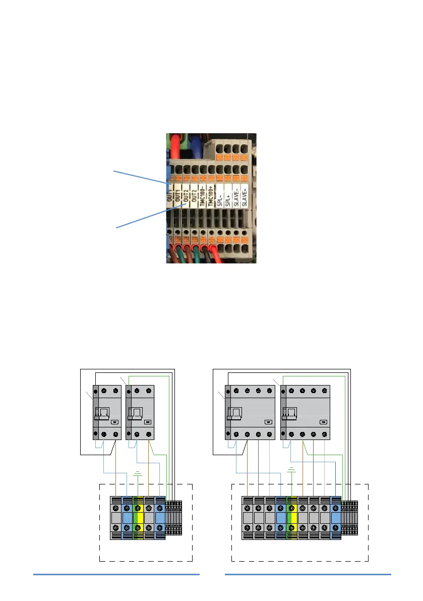
ADDITIONAL SAFETY PROTECTIONS
To ensure the electrical safety of the installation, the charging station is equipped
with a fault monitoring system of the charger switching device. This system has
potential-free outputs of 230 V ca and 5 A of maximum consumption, marked as
OUT1 and OUT2 so that in case of failure of the switching device of one line it
does not interfere with the other.
In equipment with a connection cable or socket outlet, it will only have OUT1.
In chargers with built-in protections, these OUT outputs provide a signal that
activates a device that operates on said protections, cutting off the supply
upstream.
In chargers without protections included, mechanical maneuvering devices (*re-
mote firing reel) can be connected to these OUT outputs that operate on the
external protections, cutting the supply upstream according to the following
diagram:
L1 L2
L3
N PE L1 L2
L3
N
OUT1
OUT1
OUT2
OUT2
TMC100 -
TMC100 +
L2
L3
L1N
3P + N
L2
L3
L1N
3P + N
*
*
PE L N
OUT1
OUT1
OUT2
OUT2
TMC100 -
TMC100 +
L N
L1N
1P + N
*
L1N
1P + N
*
VIARIS COMBI + 230 V~
with 2 connection cables/
power socket bases
VIARIS COMBI + 3x230/400 V~
with 2 connection cables/
power socket bases