Page
09
RS-232 IR EXTTCP/IP
DC 24V
HDMI
AUDIOOPTICAL
OUTPUT 4
HDMI
AUDIOOPTICAL
OUTPUT 3
HDMI
AUDIOOPTICAL
OUTPUT 2
HDMI
AUDIOOPTICAL
OUTPUT 1
INPUT
HDMI 1 HDMI 2 HDMI 3 HDMI 4
5
6
1
2
3
4
7
8
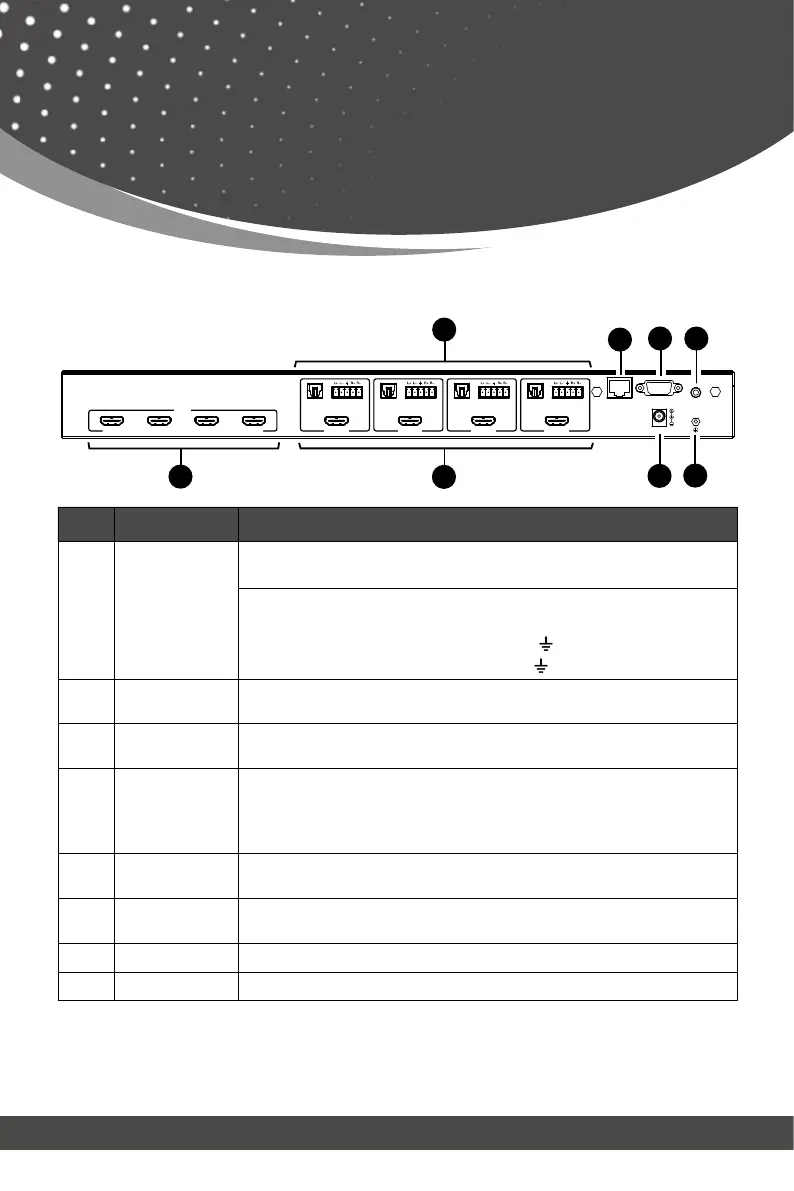
Rear Panel
Operation Controls
and Functions
No. Name Function Description
1.
AUDIO OUT
(1~4)
OPTICAL: Optical audio output port, connected to an audio
output device such as audio amplifier.
L/R AUDIO: Analog audio output port, supporting balanced/
unbalanced audio output, with a maximum support of 2Vrms.
Balanced connection method: L+, L -, , R+, R
Unbalanced connection method: L+, , R+
2. TCP/IP
TCP/IP control port, connected to PC or router with an RJ45
cable for control through Software or WebGUI.
3. RS-232 port
Connects to a PC or control system by D-Sub 9-pin cable to
4. IR EXT
If the IR receiver window of the unit is blocked or the unit is
installed in a closed area out of infrared line of sight, the IR
receiver cable can be inserted to the “IR EXT” port to receive
the IR remote signal.
5.
HDMI INPUT
HDMI input ports: Connected to a source device such as an 8K
computer, DVD or set-top box.
6.
ports (1~4)
HDMI output ports: Connected to a display device such as a
TV or monitor.
7. DC 24V Connect the included 24V/2.7A power supply.
8. GND Connect the housing to the ground.
Note:
1. You can restore the factory settings via the front panel, WebGUI or RS-232 command.
2. Power cut memory function is available except for standby status.
3. The RS-232 and WebGUI will be available few minutes after the unit is powered on.