Checking the product
11
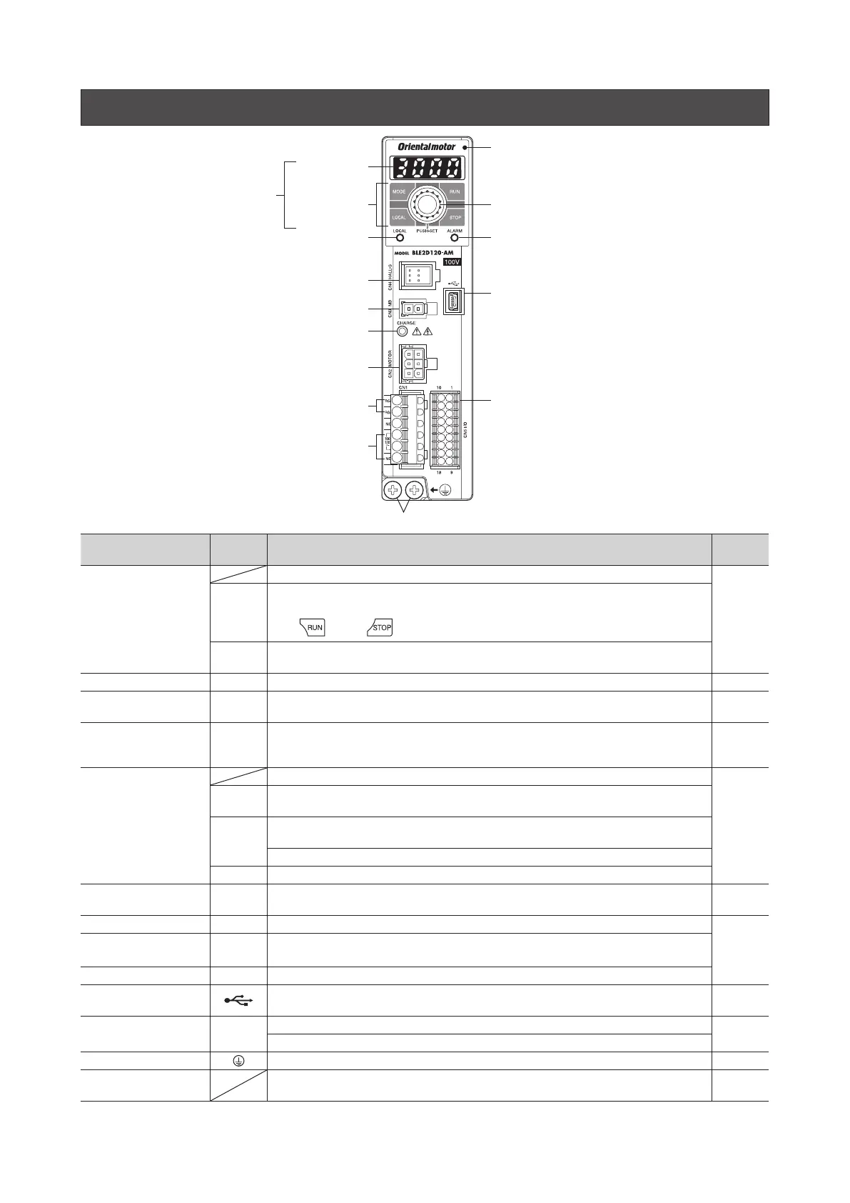
5. Names and functions of parts
Protective Earth Terminal
Main power supply input terminal
(CN1)
I/O signals connector (CN5)
Display
Operation keysSetting dial
Sensor connector (CN4)
Electromagnetic brake
connector (CN3) ∗
CHARGE LED
Motor connector (CN2)
LOCAL LED
ALARM LED
USB communication connector
Protective
lm
Use after removing the protective film
Regeneration resistor terminal
(CN1)
Item Indication Description
Reference
page
Operation panel
Display: This display shows the monitor items, setting screen, alarms, etc.
32
MODE
LOCAL
RUN
STOP
Operation keys: These keys are used to switch the operation mode or change parameters.
When the local control operation is performed, the motor can be operated and stopped
using
key and key.
PUSH-SET
Setting dial: Turn - Setting of parameter value, screen transitions
Press - Determine (SET)
LOCAL LED LOCAL This LED is lit in green when the local control operation is performed. 32
ALARM LED ALARM
This LED blinks in red when an alarm is generated.
This LED blinks in orange when information is generated. (Information
⇒
USER MANUAL)
44
CHARGE LED CHARGE
This LED is lit in red while the main power is supplied.
After the main power is turned o, the LED will turn o once the residual voltage in the
driver drops to a safe level.
−
Main power supply input
terminal (CN1)
Connects the main power supply.
14
L, N, NC
Single-phase 100-120 VAC: Connects a single-phase 100-120 VAC power supply to L and N.
NC is not used.
L1, L2, NC
L1, L2, L3
Single-phase 200-240 VAC: Connects a single-phase 200-240 VAC power supply to L1 and L2.
NC is not used.
Three-phase 200-240 VAC: Connects a three-phase 200-240 VAC power supply to L1, L2, L3.
L1, L2, L3 Three-phase 200-240 VAC: Connects a three-phase 200-240 VAC power supply to L1, L2, L3.
Regeneration resistor
terminal (CN1)
RG1, RG2 Connects the regeneration resistor (sold separately). 19
Motor connector (CN2) MOTOR Connects the power connector (white) of the connection cable.
15
Electromagnetic brake
connector (CN3)
*
MB Connects the electromagnetic brake connector (white) of the connection cable.
Sensor connector (CN4) HALL-S Connects the sensor connector (black) of the connection cable.
USB communication
connector
Connects a PC in which the
MEXE02
has been installed. 19
I/O signals connector
(CN5)
I/O
Connects input signals and output signals.
17
Connects the external potentiometer (sold separately) or external DC power supply.
Protective Earth Terminal
Connects the ground terminal of the connection cable and the grounding wire. 16
Mounting holes
(two places at the rear)
These mounting holes are used to install the driver with screws (M4). 12
*
Only drivers for electromagnetic brake motor