14
Connecting
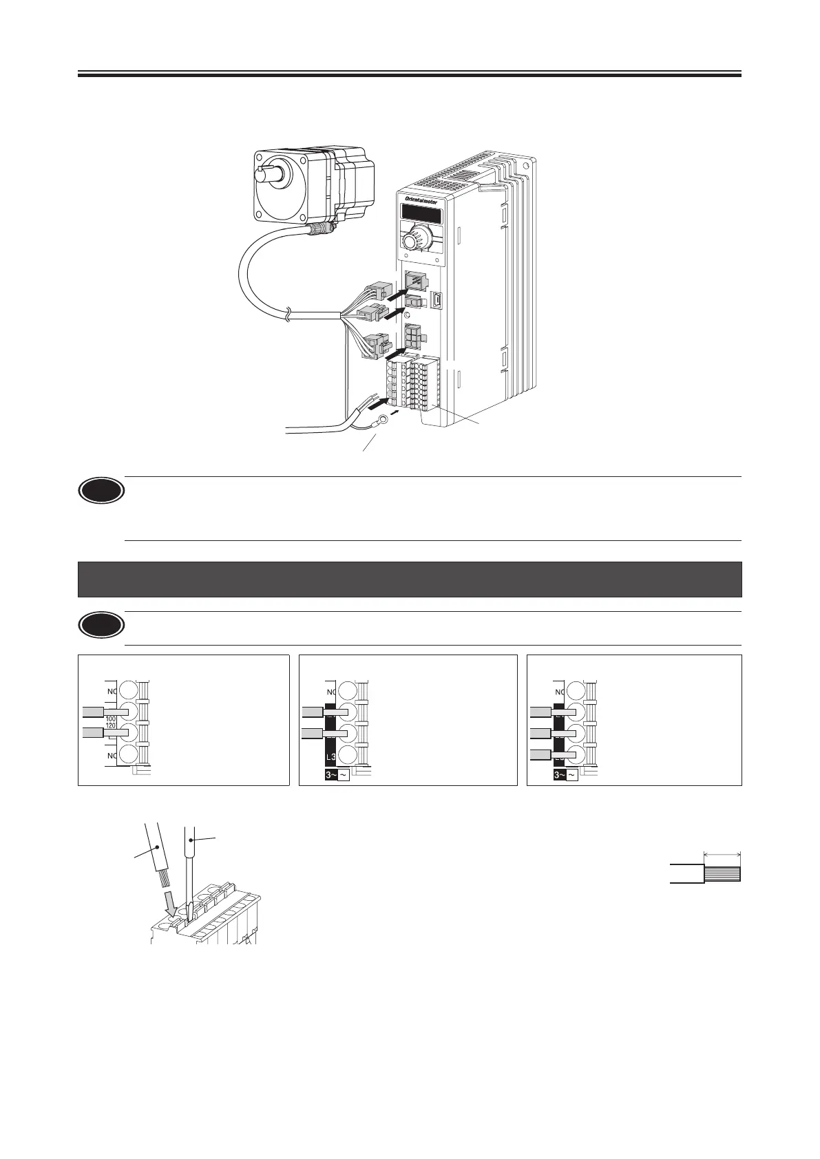
This chapter explains how to connect the motor, I/O signals and power supply to the driver, as well as grounding method using
the driver for electromagnetic brake motor.
For protection against electric shock, do not turn on the power supply until the wiring is completed.
CN4
CN2
Driver
o power supply
Ground
CN1
CN5
CN3
Note
•
Be sure to connect the connectors securely. Insecure connections may cause malfunction or damage to the motor or
driver.
•
When turning on the power again or inserting/pulling o the connector, turn o the power and wait for the CHARGE
LED to turn o before doing so. Residual voltage may cause electric shock.
1. Connecting the power supply (CN1)
Note
Check the power-supply voltage specications of the driver before applying the voltage.
If the voltage exceeding the rated range is applied, the driver may be damaged.
Single-phase 100 - 120 VAC 50/60 Hz Single-phase 200 - 240 VAC 50/60 Hz Three-phase 200 - 240 VAC 50/60 Hz
L
N
Connect the live side
to terminal L, and the
neutral side to terminal
N.
Connect the live side
to terminal L1, and the
neutral side to terminal
L2.
The motor does not
rotate if either of them
is connected to the L3
terminal.
Connect the R, S and T
phase lines to the L1,
L2 and L3 terminals,
respectively.
Connecting method
Applicable lead wire
•
Lead wire size: Stranded wire AWG18 to 14 (0.75 to 2.0 mm
2
)
•
Conductive material: Use only copper wires.
Applicable crimp terminal
Manufacturer: PHOENIX CONTACT GmbH & Co. KG
Model: AI 0,75-10 [Conductor cross-sectional area: 0.65 - 0.82 mm
2
(AWG18)]
AI 1-10 [Conductor cross-sectional area: 0.82 - 1.2 mm
2
(AWG18)]
AI 1,5-10 [Conductor cross-sectional area: 1.25 - 1.8 mm
2
(AWG16)]
AI 2,5-10 [Conductor cross-sectional area: 2.0 - 3.0 mm
2
(AWG14)]
Connector model: FKCT2,5/6-ST-5,08
(PHOENIX CONTACT GmbH & Co. KG)
Circuit breaker
Be sure to connect a circuit breaker to the power line of the driver to protect the primary circuit.
•
Rated current of protective device: 10 A
•
Recommended circuit breaker: Mitsubishi Electric Corporation NF30
Input signal
⇒
p.17
Output signal
⇒
p.17
External analog setting device
⇒
p.18
Grounding
⇒
p.16
 Loading...