EasyManua.ls Logo

Orion COMBI 3601VT - Removal of Deck Parts

Orion COMBI 3601VT
69 pages
Print Icon
To Next Page IconTo Next Page
To Previous Page IconTo Previous Page
Loading...
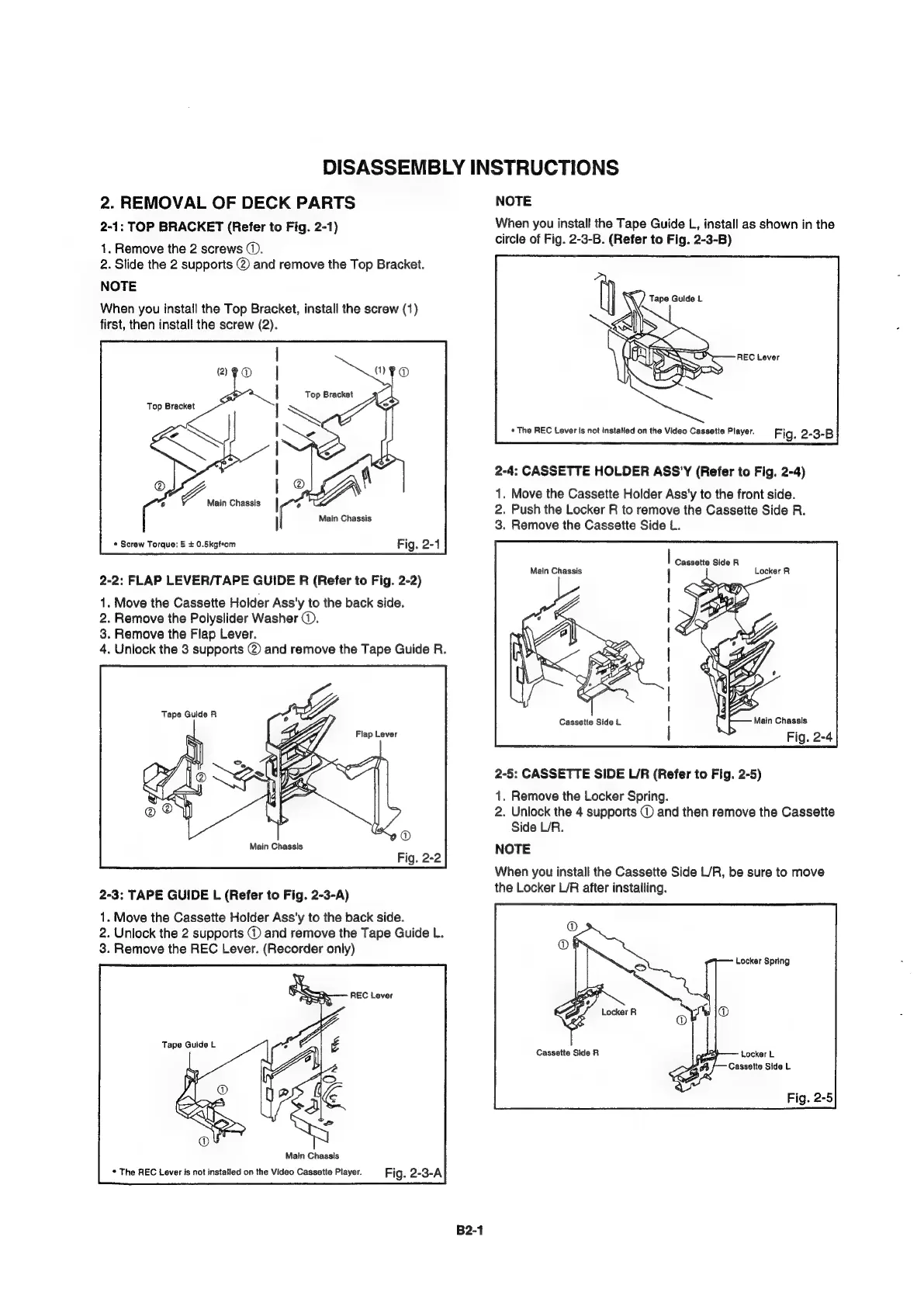
DISASSEMBLY
INSTRUCTIONS
2.
REMOVAL
OF
DECK
PARTS
2-1:
TOP
BRACKET
(Refer
to
Fig. 2-1)
1.
Remove
the
2
screws
@.
2.
Slide
the
2
supports
@
and
remove
the
Top
Bracket.
NOTE
When
you
install
the
Top
Bracket,
install
the
screw
(1)
first,
then
install
the
screw
(2).
®
C4
‘o
Main
Chassis
«
Screw
Torque:
5
+
0.5kgfecm
2-2:
FLAP
LEVER/TAPE
GUIDE
R
(Refer
to
Fig.
2-2)
1.
Move
the
Cassette
Holder
Ass'y
to
the
back
side.
2.
Remove
the
Polyslider
Washer
@.
3.
Remove
the
Flap
Lever.
4.
Unlock
the
3
supports
@
and
remove
the
Tape
Guide
R.
Main
Chassis
2-3:
TAPE
GUIDE
L
(Refer
to
Fig.
2-3-A)
1.
Move
the
Cassette
Holder
Ass'y
to
the
back
side.
2.
Unlock
the
2
supports
()
and
remove
the
Tape
Guide
L.
3.
Remove
the
REC
Lever.
(Recorder
only)
Tape
Guide
L
Main
Chassis
*
The
REC
Lever
is
not
installed
on
the
Video
Cassette
Piayer.
Fig.
2-3-A
B2-1
NOTE
When
you
install
the
Tape
Guide
L,
install
as
shown
in
the
circle
of
Fig.
2-3-B.
(Refer
to
Fig.
2-3-B)
X{)
Tape
Guide
L
as
*
The
REC
Lever
Is
not
installed
on
the
Video
Cassette
Player.
2-4:
CASSETTE
HOLDER
ASS'Y
(Refer
to
Fig.
2-4)
1.
Move
the
Cassette
Holder
Ass'y
to
the
front
side.
2.
Push
the
Locker
R
to
remove
the
Cassette
Side
R.
3.
Remove
the
Cassette
Side
L.
Main
Chassis
Main
Chassis
Fig.
2-4
Cassette
Side
L
2-5:
CASSETTE
SIDE
L/R
(Refer
to
Fig.
2-5)
1,
Remove
the
Locker
Spring.
2.
Unlock
the
4
supports
©
and
then
remove
the
Cassette
Side
L/R.
NOTE
When
you
install
the
Cassette
Side
L/R,
be
sure
to
move
the
Locker
L/R
after
installing.
Locker
Spring
Locker
L
Cassette
Side
L
Fig.
2-5