EasyManua.ls Logo

Orion COMBI 3601VT - Confirmation and Adjustment of Tape Running Mechanism

Orion COMBI 3601VT
69 pages
Print Icon
To Next Page IconTo Next Page
To Previous Page IconTo Previous Page
Loading...
MECHANICAL
ADJUSTMENTS
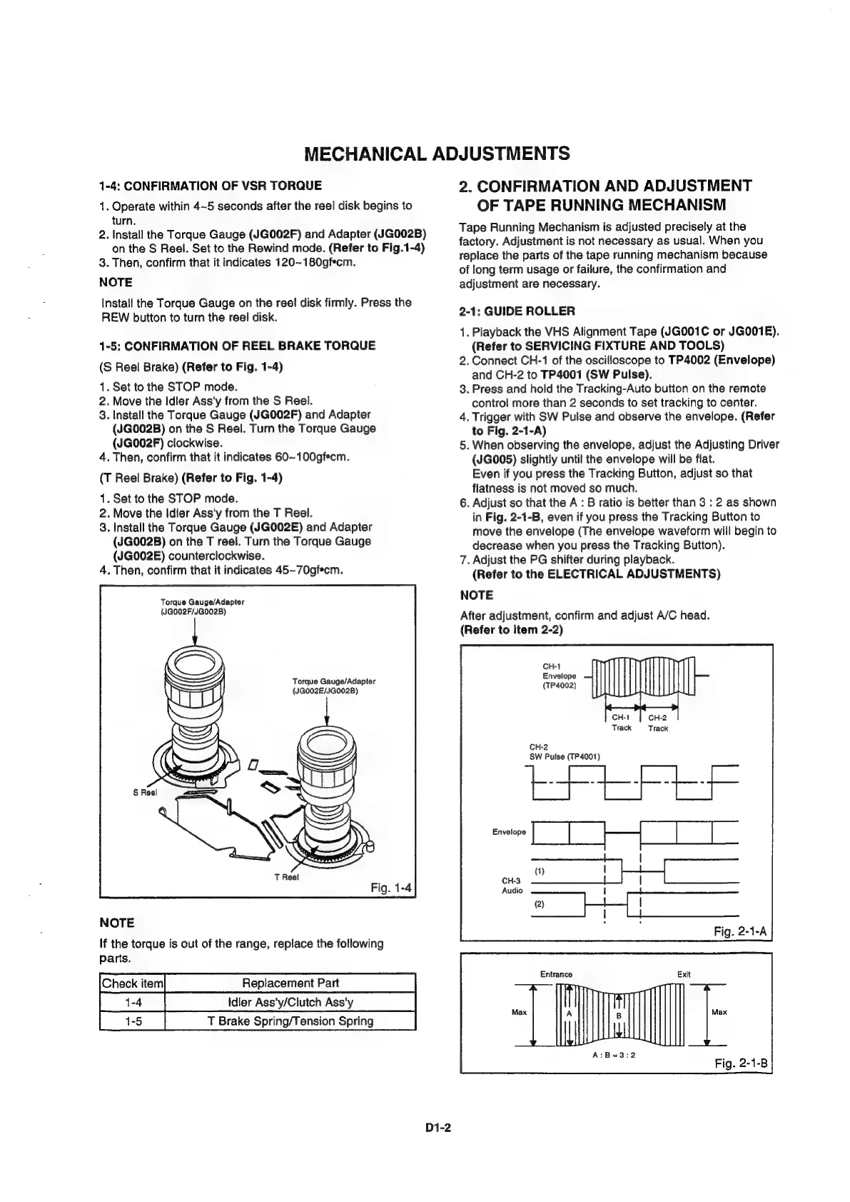
1-4:
CONFIRMATION
OF
VSR
TORQUE
1.
Operate
within
4~5
seconds
after
the
reel
disk
begins
to
turn.
2.
Install
the
Torque
Gauge
(JG002F)
and
Adapter
(JG002B)
on
the
S
Reel.
Set
to
the
Rewind
mode.
(Refer
to
Fig.1-4)
3.
Then,
confirm
that
it
indicates
120~180gfecm.
NOTE
Install
the
Torque
Gauge
on
the
reel
disk
firmly.
Press
the
REW
button
to
turn
the
reel
disk.
1-5:
CONFIRMATION
OF
REEL
BRAKE
TORQUE
(S
Reel
Brake)
(Refer
to
Fig.
1-4)
1.
Set
to
the
STOP
mode.
2.
Move
the
Idler
Ass'y
from
the
S
Reel.
3.
Install
the
Torque
Gauge
(JG002F)
and
Adapter
(JG002B)
on
the
S
Reel.
Turn
the
Torque
Gauge
(JG002F)
clockwise.
4.
Then,
confirm
that
it
indicates
60~100gfecm.
(T
Reel
Brake)
(Refer
to
Fig.
1-4)
1.
Set
to
the
STOP
mode.
2.
Move
the
Idler
Ass'y
from
the
T
Reel.
3.
Install
the
Torque
Gauge
(JG002E)
and
Adapter
(JG002B)
on
the
T
reel.
Turn
the
Torque
Gauge
(JGO02E)
counterclockwise.
4.
Then,
confirm
that
it
indicates
45~70gfecm.
Torque
Gauge/Adapter
(JGO02F/JGO02B)
Torque
Gauge/Adapter
(JG002E/JG002B)
NOTE
If
the
torque
is
out
of
the
range,
replace
the
following
parts.
Check
item
Replacement
Part
idler
Ass'y/Clutch
Ass'y
T
Brake
Spring/Tension
Spring
D1-2
2.
CONFIRMATION
AND
ADJUSTMENT
OF
TAPE
RUNNING
MECHANISM
Tape
Running
Mechanism
is
adjusted
precisely
at
the
factory.
Adjustment
is
not
necessary
as
usual.
When
you
replace
the
parts
of
the
tape
running
mechanism
because
of
long
term
usage
or
failure,
the
confirmation
and
adjustment
are
necessary.
2-1:
GUIDE
ROLLER
1.
Playback
the
VHS
Alignment
Tape
(JG001C
or
JGO01E).
(Refer
to
SERVICING
FIXTURE
AND
TOOLS)
2,
Connect
CH-1
of
the
oscilloscope
to
TP4002
(Envelope)
and
CH-2
to
TP4001
(SW
Pulse).
3.
Press
and
hold
the
Tracking-Auto
button
on
the
remote
control
more
than
2
seconds
to
set
tracking
to
center.
4.
Trigger
with
SW
Pulse
and
observe
the
envelope.
(Refer
to
Fig.
2-1-A)
5.
When
observing
the
envelope,
adjust
the
Adjusting
Driver
(JGO05)
slightly
until
the
envelope
will
be
flat.
Even
if
you
press
the
Tracking
Button,
adjust
so
that
flatness
is
not
moved
so
much.
6.
Adjust
so
that
the
A
:
B
ratio
is
better
than
3
:
2
as
shown
in
Fig.
2-1-B,
even
if
you
press
the
Tracking
Button
to
move
the
envelope
(The
envelope
waveform
will
begin
to
decrease
when
you
press
the
Tracking
Button).
7.
Adjust
the
PG
shifter
during
playback.
(Refer
to
the
ELECTRICAL
ADJUSTMENTS)
NOTE
After
adjustment,
confirm
and
adjust
A/C
head.
(Refer
to
item
2-2)
CH-1
Envelope
(P4002)
CH-1
CH-2
Track
Track
CH-2
SW
Pulse
(TP4001)
oe
a
eas
Ce
(1)
(2)
Entrance
Exit
‘Tm
A:B=3:2
Fig.
2-1-B