EasyManua.ls Logo

Orion COMBI 3601VT - Page 16

Orion COMBI 3601VT
69 pages
Print Icon
To Next Page IconTo Next Page
To Previous Page IconTo Previous Page
Loading...
DISASSEMBLY
INSTRUCTIONS
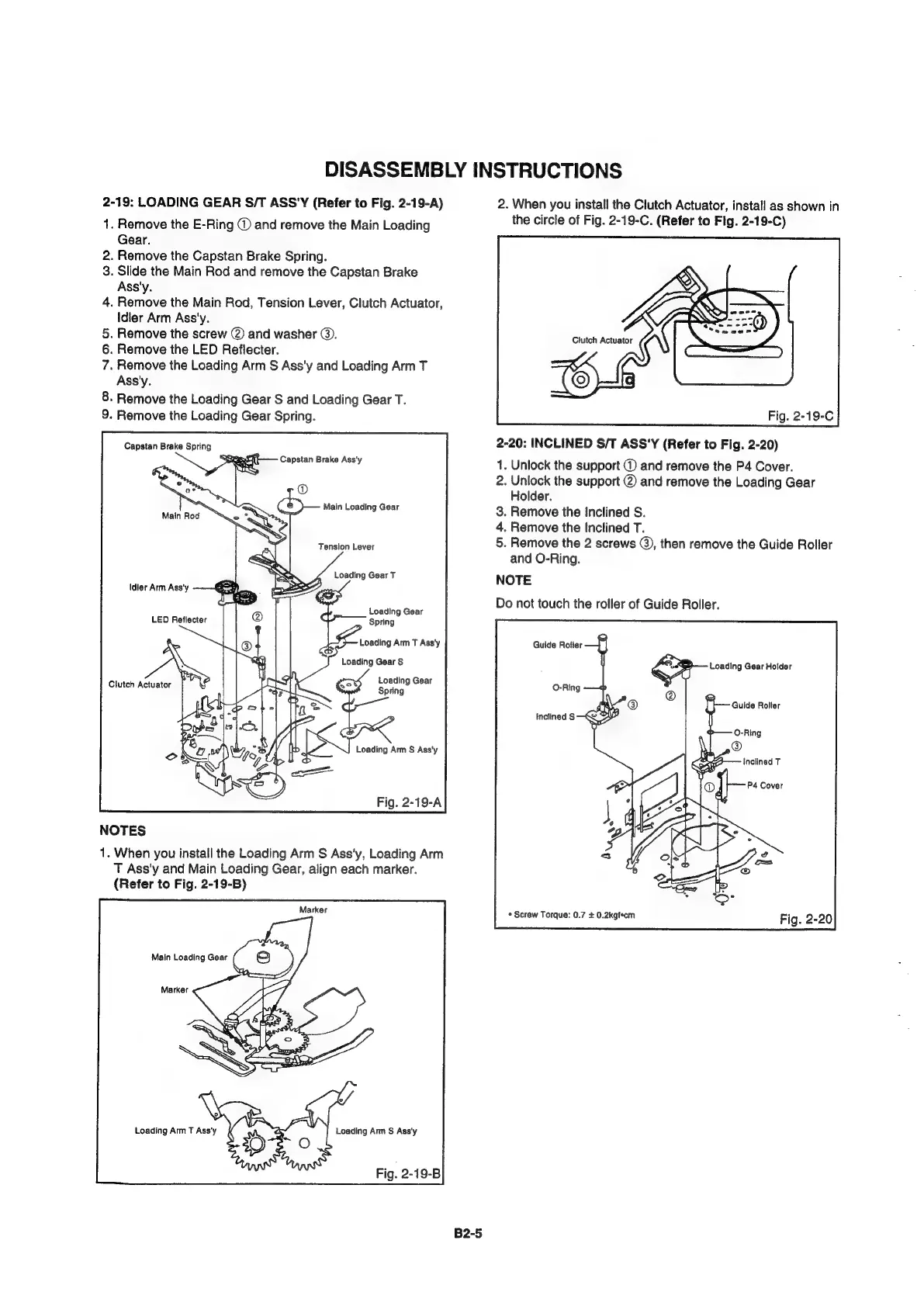
2-19:
LOADING
GEAR
S/T
ASS'Y
(Refer
to
Fig.
2-19-A)
1.
Remove
the
E-Ring
©
and
remove
the
Main
Loading
Gear.
.
Remove
the
Capstan
Brake
Spring.
.
Slide
the
Main
Rod
and
remove
the
Capstan
Brake
Ass'y.
.
Remove
the
Main
Rod,
Tension
Lever,
Clutch
Actuator,
Idler
Arm
Ass'y.
.
Remove
the
screw
@
and
washer
©.
.
Remove
the
LED
Reflecter.
.
Remove
the
Loading
Arm
S
Ass'y
and
Loading
Arm
T
Ass'y.
-
Remove
the
Loading
Gear
S
and
Loading
Gear
T.
.
Remove
the
Loading
Gear
Spring.
Capstan
Brake
Spring
Main
Loading
Gear
Tension
Lever
Loading
Gear
T
Idler
Arm
Ass'y
Loading
Gear
LED
Reflecter
Spring
Loading
Arm
T
Ass'y
Loading
Gear
S
Loading
Gear
Spring
Loading
Arm
S
Ass'y
Fig.
2-19-A
NOTES
1.
When
you
install
the
Loading
Arm
S
Ass'y,
Loading
Arm
T
Ass'y
and
Main
Loading
Gear,
align
each
marker.
(Refer
to
Fig.
2-19-B)
Marker
Main
Loading
Gear
2.
When
you
install
the
Clutch
Actuator,
install
as
shown
in
the
circle
of
Fig.
2-19-C.
(Refer
to
Fig.
2-19-C)
2-20:
INCLINED
S/T
ASS'Y
(Refer
to
Fig.
2-20)
1.
Unlock
the
support
@
and
remove
the
P4
Cover.
2.
Unlock
the
support
@
and
remove
the
Loading
Gear
Holder.
8.
Remove
the
Inclined
S.
4.
Remove
the
Inclined
T.
5.
Remove
the
2
screws
@),
then
remove
the
Guide
Roller
and
O-Ring.
NOTE
Do
not
touch
the
roller
of
Guide
Roller.
*
Screw
Torque:
0.7
+
0.2kgfecm
B2-5