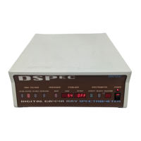
DSPEC
®
Digital Gamma-Ray Spectrometer
18
Front-Panel LEDs
ACCEPT
Green LED indicates an input has been processed.
REJECT
Red LED indicates an input has been rejected.
DEADTIME
7-segment LED indicates system dead time, 0 to 99%.
POWER
Front-panel LED indicates system power is ON.
5.1.2. Inputs and Outputs
INPUT
Rear-panel BNC accepts preamplifier signals of either polarity, with rise times less
than the selected Flattop Time setting and exponential decay time constant in the range of 40 µs
to infinity (including transistor-reset and pulsed-optical reset preamplifiers). Input impedance
>500 , input is dc-coupled and protected to ±25 V.
ADC GATE
Rear-panel BNC accepts slow positive NIM input; computer selectable as
coincidence or anti-coincidence. ADC GATE must overlap and precede the flattop region by
0.5 µs, and extend beyond the flattop region by 0.5 µs. The InSight Oscilloscope allows easy
alignment of the ADC GATE signal with the digital output pulse.
TRP INHIBIT
Rear-panel BNC connector accepts reset signals from transistor-reset (TRP) or
pulsed-optical (OF) preamplifiers. Positive NIM logic or TTL level can be used. Inhibit input
initiates the protection against distortions caused by preamplifier reset. This includes turning off
the baseline restorer, monitoring the overload recovery, and generating the pile-up reject and
busy signals for the duration of the overload. These last two signals are used internally to
provide information to the dead-time correction circuitry.
HIGH VOLTAGE OUTPUT
Rear-panel SHV connector, 0–5 kV (Z
o
= 2 M). Computer-
sensed.
REMOTE SHUTDOWN
Rear-panel BNC is used to turn off the bias supply voltage in the
event that the detector warms up. This remote shutdown is compatible with any ORTEC
detector. The REMOTE SHUTDOWN must be connected to the Bias Shutdown of the detector,
or the high voltage will not turn on. For use with a detector with an incompatible shutdown
circuit, this feature can be defeated by placing a 100-, 50-, or 0- terminator on the REMOTE
SHUTDOWN input.