2. GETTING STARTED
5
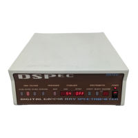
Under the cooling fan is the power input block, into which is plugged an international standard
AC power cord suitable for local power distribution. A small printed circuit board can be
accessed behind a sliding plastic window. This board can be inserted in four different ways,
allowing you to select 100, 120, 220, or 240 volts. The selected voltage is the only one that can
be read through the window. The correct fuse size, power cord, and voltage setting are supplied
with the instrument.
PREAMP POWER
, both ±12 and ±24 volts DC, is provided via a standard 9-pin D-type
connector.
The
HIGH VOLTAGE
section has three components. A 10-turn potentiometer sets the value of
the detector bias. A BNC connector receives the signal indicating a warmed-up detector,
requiring removal of detector bias. The
OUTPUT
connector is an SHV-type connector carrying
the detector bias voltage.
The next section has three BNC connectors. The
INPUT
connector receives the low-level
analog signal from the preamplifier. The
ADC GATE
connector is an input which can be used
to cause the system to accept or reject a pulse under the control of external electronics. The
TRP
INHIBIT
is an input used to reject pulses during the reset period of detectors with transistor-
reset preamplifiers.
CHANGE SAMPLE
is a logic output used to control sample changers.
SAMPLE READY
is a
logic input used to report that the sample changer has completed changing the sample. (Use of
these features requires software support discussed in the software manuals.)
Connection to the computer is by means of either the
DUAL-PORT MEMORY
37-pin D-Type
connector or the
ETHERNET
BNC connector. Most new systems will use the more convenient
Ethernet connection; the Dual-Port Memory method is provided for compatibility with existing
systems. The
RS-232-C
connector provides a low-speed serial link to the PC and is normally not
used.
2.4. Internal Switches
NOTE
If you are using P-type detectors, such as ORTEC’s GEM Series, or if you have
purchased a complete system, you may skip the remainder of this section.
There are two internal settings which must be correctly set for your particular type of detector.
Changing these settings requires removal of the DSPEC cover: