3
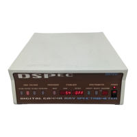
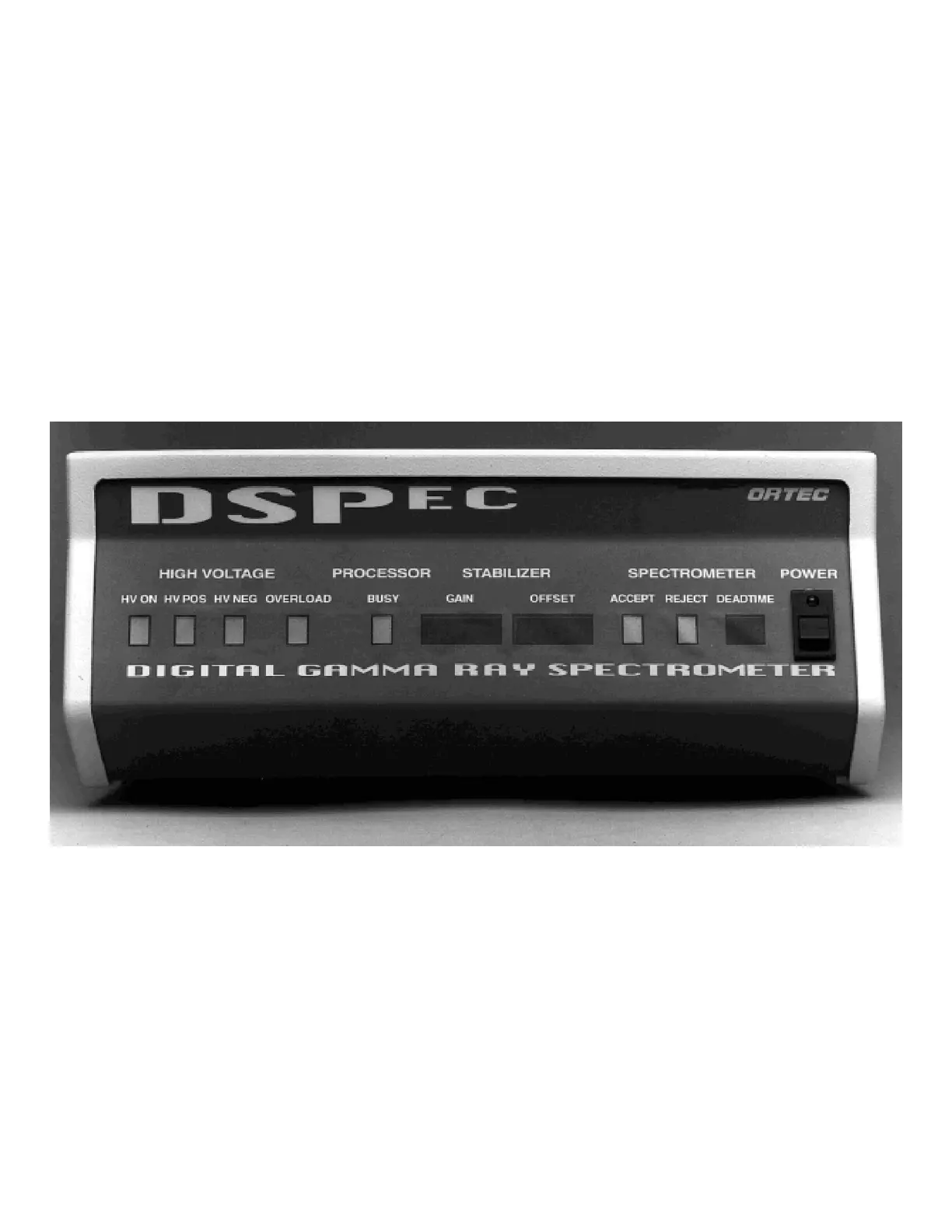
Fig. 1. DSPEC Front Panel.
2. GETTING STARTED
2.1. What You Will Learn in this Chapter
In this chapter you will:
Become acquainted with the DSPEC front- and rear-panel indicators and controls.
Set the electrical power input for your local conditions.
Learn whether you need to change the factory settings of the internal switches.
2.2. The Front Panel
Figure 1 shows the DSPEC front panel.
Starting from the left, there are four LEDs indicating the status of the detector bias supply.
Illumination of the
HV ON
light indicates that the rear-panel high voltage connector is powered.
Either the
HV POS
or
HV NEG
light will be illuminated to show the internal setting of the
detector bias polarity switch.
The
OVERLOAD
light indicates that the power supply is overloaded and shut down. (This
condition usually indicates a shorted output due to a faulty cable or improper connection.)
The
PROCESSOR BUSY
light flashes to indicate functions of the internal microprocessor.