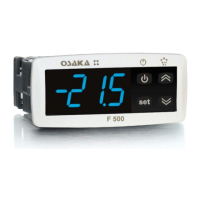
OSAKA – USER MANUAL – F 500 / F 500-RS – V.1 – Page 1
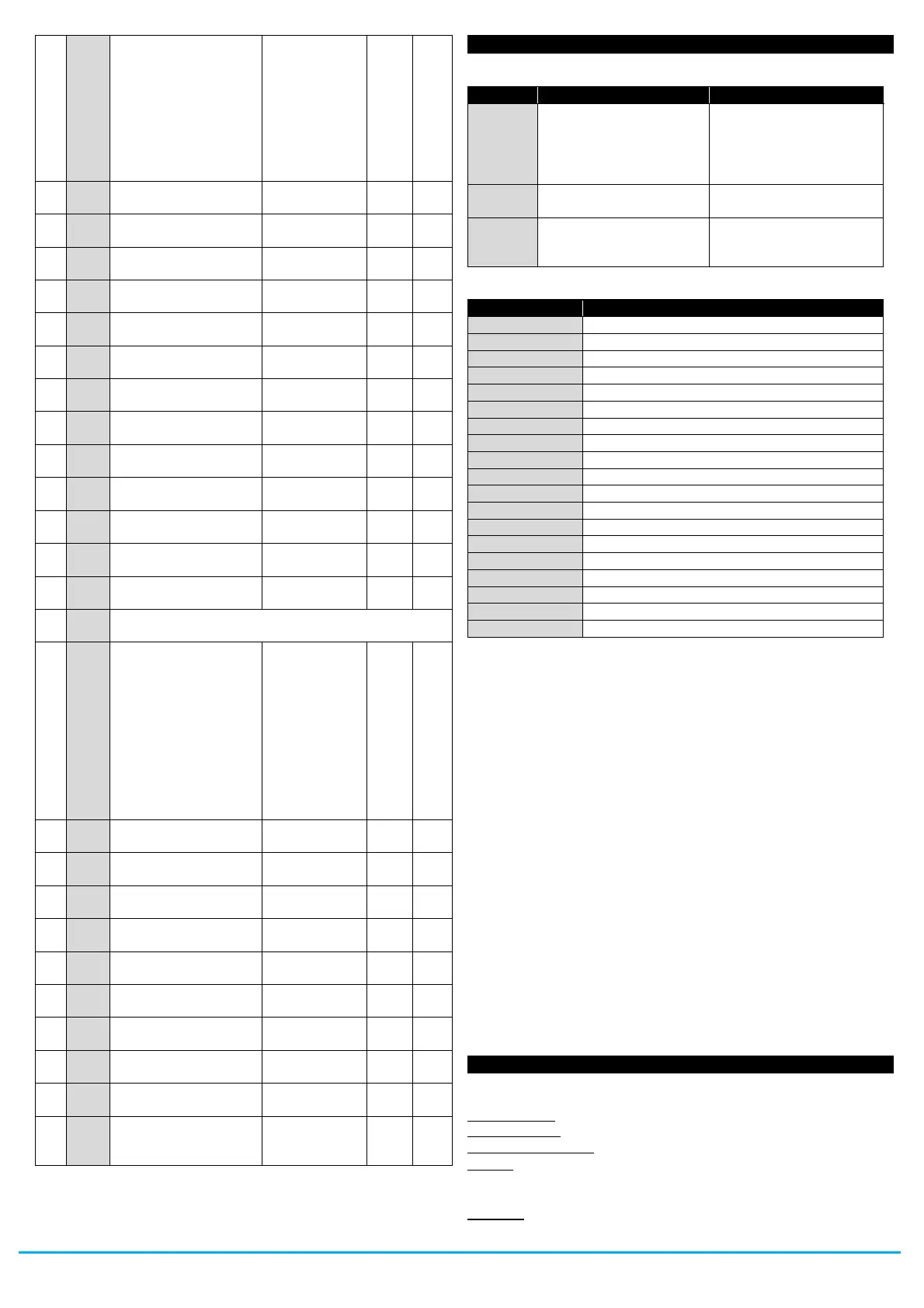
t.3 = Switch on Aux
output
t.4 = Switch off Aux
output
t.5 = Start defrost
t.6 = Switch to Eco
mode (SPE)
t.7 = Switch to normal
mode (SP)
H. - parameters relative HACCP stored alarms
(read only parameters)
Stored Alarm n. 1:
A. = Alarm type
y.= start year
M.= start month
d.= start date
h. = start hour
n. = start min.
E. = duration(hrs)
e. = duration (min.)
_= peak max./min.
(critical temp.) °C/°F
A. = H1/ L1/
H2/ L2/ bo/ AL
y. = 10 ÷ 99
M. = 1 ÷ 12
d. = 1 ÷ 31
h. = 0 ÷ 23
n. = 0 ÷ 59
E. = 0 ÷ 99
e. = 0 ÷ 59
_ = - 99.9 ÷
999
Number of HACCP
alarms deleted
because exceeded
(#) : Only in models with Real Time Clock
6 - PROBLEMS, MAINTENANCE AND GUARANTEE
6.1 - SIGNALLING
E1 -E1
E2 -E2
E3 -E3
E4 -E4
The probe may be
interrupted (E) or in
short circuit (-E), or may
measure a value outside
the range allowed
Check the correct
connection of the probe
with the instrument and
check the probe works
correctly
Internal EEPROM
memory error
Replace the instrument
or ship to factory for
repair
Other Signalling:
Delay at power-on in progress
Maximum temperature alarm 1 in progress
Minimum temperature alarm 1 in progress
Maximum temperature alarm 2 in progress
Minimum temperature alarm 2 in progress
Digital input alarm in progress
Digital input alarm PrA in progress
Digital input alarm HP in progress
Digital input alarm LP in progress
Defrosting in progress with “d.dL”=Lb
Post-defrosting in progress with “d.dL”=Lb
As-yet unrecognised HACCP alarms occurring
Reset/delete peak values and HACCP alarms
HACCP Alarms rec. disable
6.2 - CLEANING
We recommend cleaning of the instrument only with a slightly wet
cloth using water and not abrasive cleaners or solvents.
6.3 - GUARANTEE AND REPAIRS
This device has a guarantee in form of repair or replacement by
manufacturing defects in materials of 12 months from the date of
purchase.
OSAKA SOLUTIONS automatically void this guarantee and is not
liable for any damages deriving from:
- Use, installation, or use and handling undue, others than
those described above and, in particular, differs from the
safety requirements established by the regulations.
- Use in applications, machines or electrical panels that do not
provide adequate protection against liquids, dust, grease and
electric shocks to the installation conditions made.
- The inexperienced handling, and / or alteration of the product.
- The installation / use in applications, machines or electrical
panels do not comply with the valid norm.
In case of defective product under warranty or out of that period, it
should contact the post sales service to perform the necessary
steps. Request document repair "RMA" (by mail or fax) and
complete it, is necessary send the RMA and the device to SAT
OSAKA by method prepaid.
7.1 - ELECTRICAL DATA
Power supply: 100...240 VAC +/- 10%
Frequency AC: 50/60 Hz
Power consumption: 6 VA approx.
Input/s: 4 inputs for temperature probes: PTC (KTY 81-121, 990
@ 25 °C) or NTC (103AT-2, 10K @ 25 °C) or Pt1000 (1000 @
0° C); 2 digital inputs for free voltage contacts
Output/s: up to 4 relay outputs (Out1 and Out2 are always present)


 To Next Page
 Loading...