OSAKA – USER MANUAL – F 500 / F 500-RS – V.1 – Page 1
In the event of unrecognised (and therefore still ongoing) HACCP
alarms, the instrument displays the message “HAC” alternating
with the normal display.
Within the parameter the data will be displayed sequentially as the
SET key is repeatedly pressed.
The alarm is deleted by holding down the Down key for more than 5
seconds while one of the data of the alarm is displayed.
Similarly the value of the “H.dL” parameter can be reset by holding
down the Down key for more than 5 seconds while the value is
being displayed)
For HACCP alarm configuration and operation, see the relevant
section.
3 - INFORMATION ON INSTALLATION AND USE
3.1 - PERMITTED USE
The instrument has been projected and
manufactured as a measuring and control device
to be used according to EN60730-1 for the
altitudes operation until 2000 ms. The use of the
instrument for applications not expressly permitted
by the above mentioned rule must adopt all the necessary
protective measures.
The instrument CANNOT be used in dangerous environments
(flammable or explosive) without adequate protection.
The instrument used with NTC 103AT11 probe (identifiable by the
printed code “103AT-11” visible on the sensor part) or Pt1000 is
compliant with standard EN 13485 ("Thermometers for measuring
the air and product temperature for the transport,storage and
distribution of chilled, frozen, deep-frozen/quick-frozen food and ice
cream”) with the following classification: [EN13485 air, S, A, 1,-
50°C +90°C]
Remember that the end user must periodically checks and verify the
thermometers in compliance with standard EN 13486.
The installer must ensure that EMC rules are respected, also after
the instrument installation, if necessary using proper filters.
Whenever a failure or a malfunction of the device may cause
dangerous situations for persons, thing or animals, please
remember that the plant has to be equipped with additional devices
which will guarantee safety.
3.2 - MECHANICAL MOUNTING
The instrument, in case 78 x 35 mm, is designed for flush-in panel
mounting. Make a hole 71 x 29 mm and insert the instrument, fixing
it with the provided special brackets. We recommend that the
gasket is mounted in order to obtain the front protection degree as
declared. Avoid placing the instrument in environments with very
high humidity levels or dirt that may create condensation or
introduction of conductive substances into the instrument. Ensure
adequate ventilation to the instrument and avoid installation in
containers that house devices which may overheat or which may
cause the instrument to function at a higher temperature than the
one permitted and declared. Connect the instrument as far away as
possible from sources of electromagnetic disturbances such as
motors, power relays, relays, solenoid valves, etc.
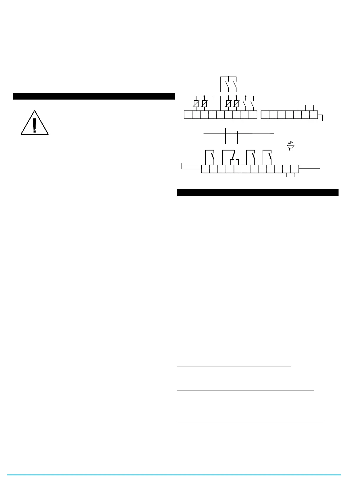
3.3 - ELECTRICAL CONNECTION
Carry out the electrical wiring by connecting only one wire to each
terminal, according to the following diagram, checking that the
power supply is the same as that indicated on the instrument and
that the load current absorption is no higher than the maximum
electricity current permitted. As the instrument is built-in equipment
with permanent connection inside housing, it is not equipped with
either switches or internal devices to protect against overload of
current: the installation will include an overload protection and a
two-phase circuit-breaker, placed as near as possible to the
instrument, and located in a position that can easily be reached by
the user and marked as instrument disconnecting device which
interrupts the power supply to the equipment. It is also
recommended that the supply of all the electrical circuits connected
to the instrument must be protect properly, using devices (ex. fuses)
proportionate to the circulating currents. It is strongly recommended
that cables with proper insulation, according to the working voltages
and temperatures, be used. Furthermore, the input cable of the
probe has to be kept separate from line voltage wiring. If the input
cable of the probe is screened, it has to be connected to the ground
with only one side. We recommend that a check should be made
that the parameters are those desired and that the application
functions correctly before connecting the outputs to the actuators so
as to avoid malfunctioning that may cause irregularities in the plant
that could cause damage to people, things or animals.
3.4 - ELECTRICAL WIRING DIAGRAM
4.1 - ON / STAND-BY FUNCTION
The instrument, once powered up, can assume 2 different
conditions:
- ON : means that the controller uses the control functions.
- STAND-BY : means that the controller does not use any control
function and the display is turned off except for the Stand-by led.
If there is no power, and then power returns, the system always
sets itself in the condition it was in before the black-out.
The ON/Stand-by function can be selected:
- Pressing the Key STAND-BY for at least 1 sec. if the parameter
"t.UF" = 3 or 5
-Pressing the key DOWN/AUX for at least 1 sec. if the parameter
"t.Fb" = 3 or 5
- using the digital input if the parameter “i.xF” = 7 or 15
- by programming a programmable event through the clock (if
present)
4.2 - "NORMAL", "ECONOMICAL" AND "TURBO" OPERATING
MODES
The instrument can be used to enter up to 3 different regulating set
points: Normal - “SP”; Economical - “SPE”; and “Turbo” - “SPH”.
Associated with each of these is the corresponding differential
(hysteresis): normal - “r.d”; Economical - “r.Ed”; and “Turbo” -
“r.Hd”.
Switching between the various modes can be automatic or manual
"NORMAL-ECONOMICAL" MODE OPERATION
Can be used where it is necessary to switch between two different
operating temperatures (e.g. day/night or working days/holidays)
NORMAL/ECONOMICAL mode can be selected manually:
– by pressing the STAND-BY key if parameter "t.UF" = 2
– by pressing the DOWN/AUX key if parameter "t.Fb" = 2
– by a digital input if parameter “i.xF” = 6
NORMAL/ECONOMICAL mode can be selected automatically:
– after the door has been closed for time “i.Et” (switching from
Norm. to Eco)
– when the door is opened if the SPE set point is active from
parameter “i.Et” (switching from Eco to Norm.)
- after the door has been closed for time “i.tt” since activation of the
SPE set point from parameter “i.Et” (switching from Eco to Norm.)
- at times defined through the clock by programming events t.6
(switch to Eco mode) and t.7 (switch to normal mode). For further
8
2 A G en .U se
1 0 A R e s .
1 2 A R e s. 3 0 L R A / 5 F L A
UL
22
O ut2
O ut1
X 3 4
2118 19 2017
NCC NO
O ut2 :
O ut1 :
O ut3 ,4:
8 (3) A
1 6 (9 ) A 1 0 (4) A
4 (4) A
2 (1) A5 (1) A
EN
6 1 8 10
EN
6 0 7 30
4321 75 6
IN P U TS
O ut4O ut3
B U Z Z E R
24 25 26 282723
S U P P LY
15
IN T E RN A L
1 0 E 5 cy c le s , 0 T 5 0 °C
11109 1412 13 16
P r1
P r2
P r3 P r4
d i3 d i4
R S 4 85
d i1 d i2
D-D+
G N D


 To Next Page
 Loading...