Page 13
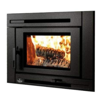
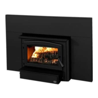
Product Specication Manual - Osburn 1700-I
ENGLISH
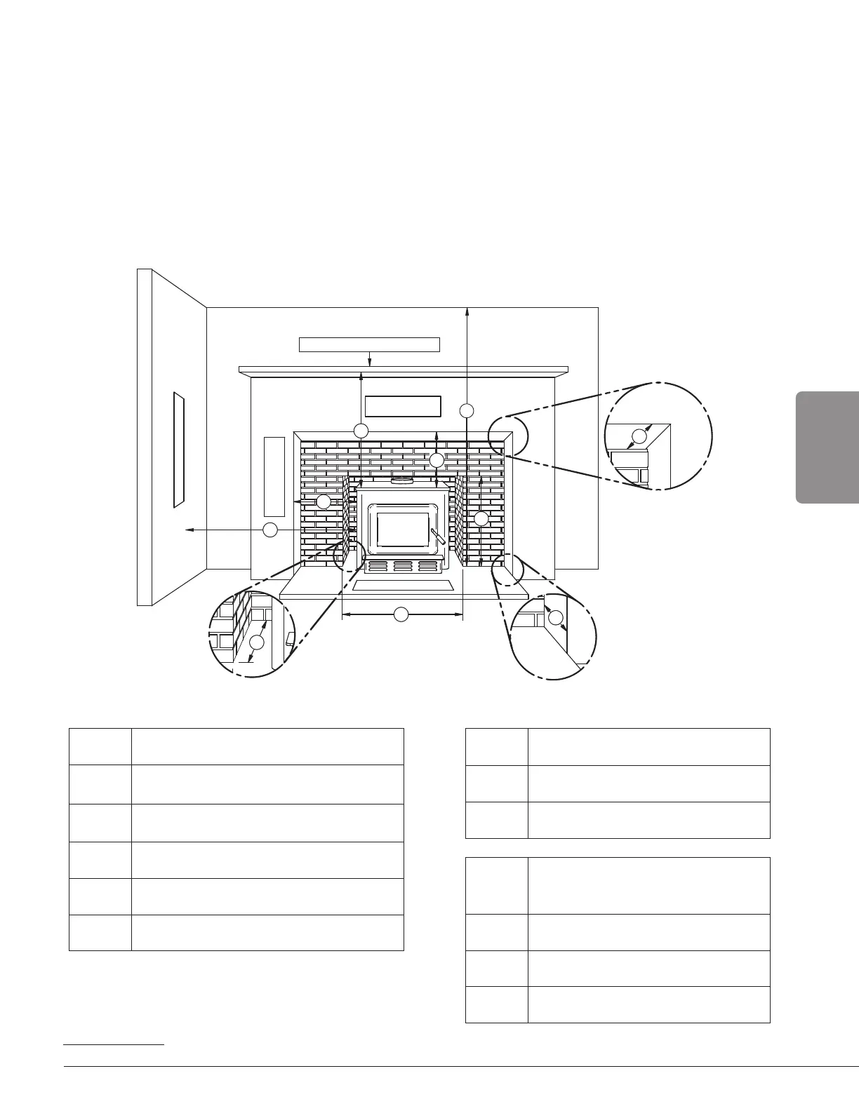
3. Clearances to Combustible Material
When the insert is installed so that its surfaces are at or beyond the minimum clearances
specified, combustible surfaces will not overheat under normal and even abnormal operating
conditions.
NO PART OF THE INSERT MAY BE LOCATED CLOSER TO THE COMBUSTIBLE THAN THE MINIMUM
CLEARANCE FIGURES GIVEN.
CLEARANCES MAY ONLY BE REDUCED BY MEANS APPROVED BY THE REGULATORY AUTHORITY.
3.1 Minimum Masonry Opening and Clearances to Combustibles
COMBUSTIBLE MANTEL SHELF
COMBUSTIBLE
TOP SURROUND
COMBUSTIBLE
SIDE SURROUND
ADJACENT SIDE WALL
FLOOR PROTECTION
J
I
H
Q
G
F
K
L
O
P
Masonry Opening and Clearances
MINIMUM CLEARANCES
F 16" (406 mm)
G 9" (229 mm)
H 27" (686 mm)
I 27" (686 mm)
Q 84" (213 cm)
MAXIMUM THICKNESS
O 5" (127 mm)
P 12" (305 mm)
MINIMUM MASONRY
OPENING
J 21 ½" (546 mm)
K
1
27 ½" (700 mm)
L
12 ⅞ (328 mm)
1
If a fresh air intake is required, it is recommended to add at least 4" to the width of the minimum opening of the hearth.
 Loading...