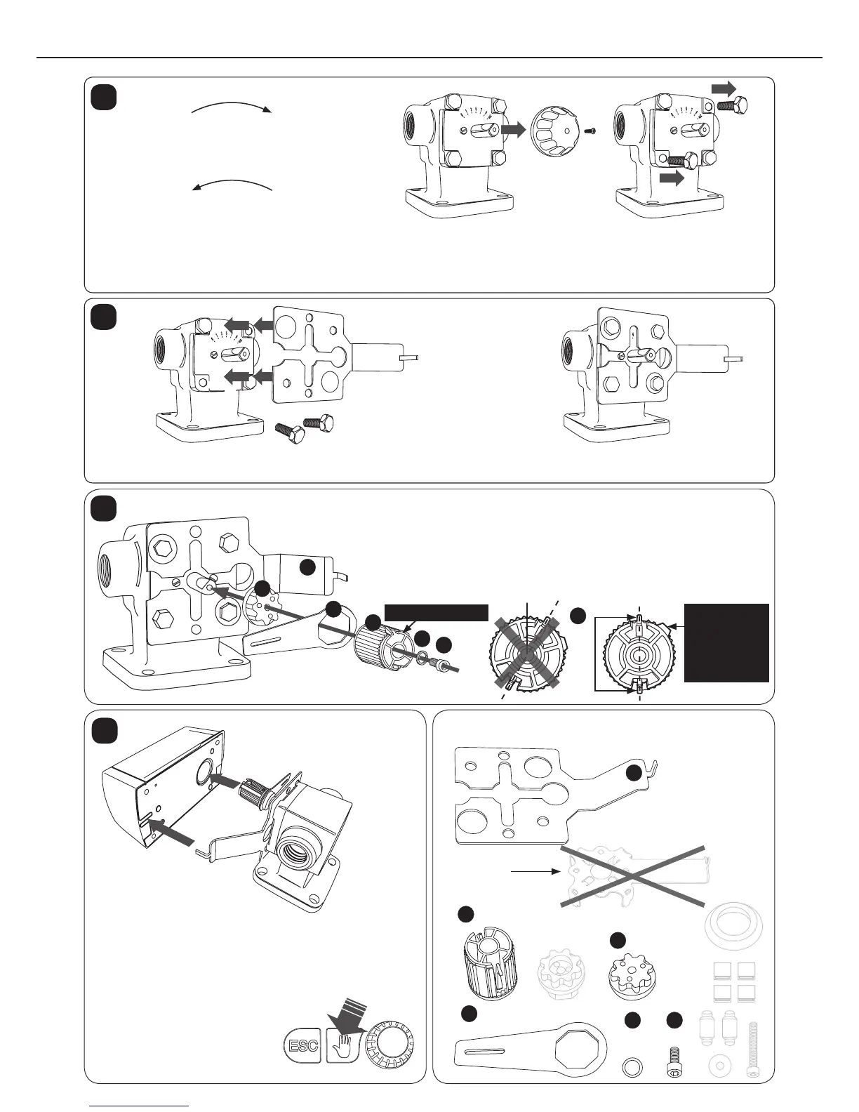
5
Install the shaft tting on the valve shaft while observing the shaft bevel. In-
stall the manual operation lever on the axle of the shaft tting, pointing hori-
zontally to the left (9 o’clock). Place the gear tting to the shaft tting so that
the manual operation lever is between the ttings and the gear tting pin-
ions point up and downwards. The alignment surface of the tting
should point towards 2 o’clock. Fix the parts to the valve shaft with the
screw and washer.
3
D
А
B
C
D
E
F
Alignment surface
Fitting pinions
NOTE!
The align-
ment surface
should point
to this
direction.
Fasten the installation bracket to the valve using the cover screws as shown in the diagram. The installation bracket has
several holes. Use the ones that match the valve type.
2
Use the manual control knob to turn the valve all the way to the left, so the valve is either completely open or clo-
sed. The regulator direction of the valve opening counter-clockwise should be changed according to Section
12 (regulator installed). Turn scale plate if needed. Remove the manual control knob and detach the two cover sc-
rews from the valves.
Valve opens clockwise
Valve opens counterclockwise
1
Closed
Closed
Open
Open
Use the manual control lever to check that the
valve turns freely over the full range of
movement (90°). You must press
the manual control knob while
you are turning the manual
control lever.
Attach the regulator according to the illustrations, en-
suring that the gear tting alignment surfaces face the
regulator and the installation plate pegs are placed cor-
rectly.
4
D
Shaft tting
Manual operation lever
Gear tting
B
C
Washer
E
Screw
F
Installation plate
SOV-VALURAUTA
А
This plate is
not used!
Go to Section 4 (Page 9)
ESBE BOILER VALVE, CAST IRON/TERMOMIX
Contents of the installation package
(Use only indicated parts!)
 Loading...