9
EH-800 CONNECTIONS
24 V
AC/DC
Plug one end of the cord into the wall and the other end into the controller. We recommend putting the cord
in a protective sleeve. Put the connection space’s protective cover back into place.
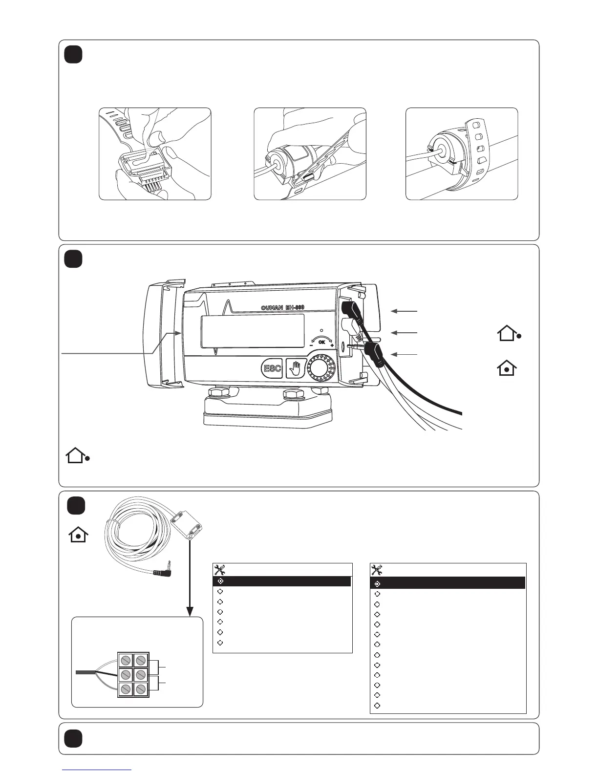
7
Connect the cord and connecting box if you take something that is not included in
the basic package into use (e.g., room sensor or something else mentioned be-
low). The cord and connecting box can be used to connect 2 different things (measure-
ments 3 and 4).
Open the connecting box and make the necessary connections (see the list below).
Select the use for measurements 3 and 4. (section 11) during controller initialization
(heating controller use).
Connecting box
Meas. 3
Meas. 4
White
Black
Red
6
Measurement 3
Not in use
TMR Room measurement
TMR / SP Room measurement
Return water
Temperatur of accumulator
Temperature of boiler
Measurement 3 (labelled)
Measurement 4
Not in use
TMR / SP Room temp.potentiometer
Home/Away -switch
Return water
TMR / P Room compensation
Temperatur of accumulator
Temperature of boiler
Measurement 4 (labelled)
Pressure alarm
Burner alarm
Pump alarm
Boiler alarm
Alarm (labelled)
Detach the protective cover of the controller’s connection space (slides off at a right angle to the controller)
and connect the outdoor sensor to the controller.
Power source
GSM modem and
EXU-800 external
unit connection
(see separate
instructions)
Additional connections
using the cord and
connecting box
(measurements 3 and 4)
Outdoor sensor
Position the outdoor sensor (TMO) in a shady place on the northern side of the building at a height
of about 2.5 meters. Do not install the sensor directly above a window, door, vent or sensor cable protection tube
coming from indoors, or next to an exhaust duct or any other source of heat. If necessary, the cable can be either
shortened or lengthened using a screw connector. (No special requirements for cable type).
24 V
AC/DC
5
Fasten the surface sensor to the surface of the pipe entering the network about 0.5...1.5 m from
the valve either on the top or side of the pipe. The surface of the pipe should be clean, rust free and smooth; the
pipe can be painted.
H1 Supply water sensor
Is already attached to the controller.
H2 Supply water sensor Connect/ is already attached the external unit to the controller using the RJ45-2.
Cut the corner of the bag open
and squeeze the grease on the
bottom surface of the sensor
(cooper plate).
Wrap the fastening strap
around the pipe. Make sure
that that the surface sensor is
not loose.
Wrap the strap around the pipe
again if it is long enough. Cut the
strap to the proper length along
the groove between the holes.
4

 Loading...