7
Go to Section 4 (Page 9)
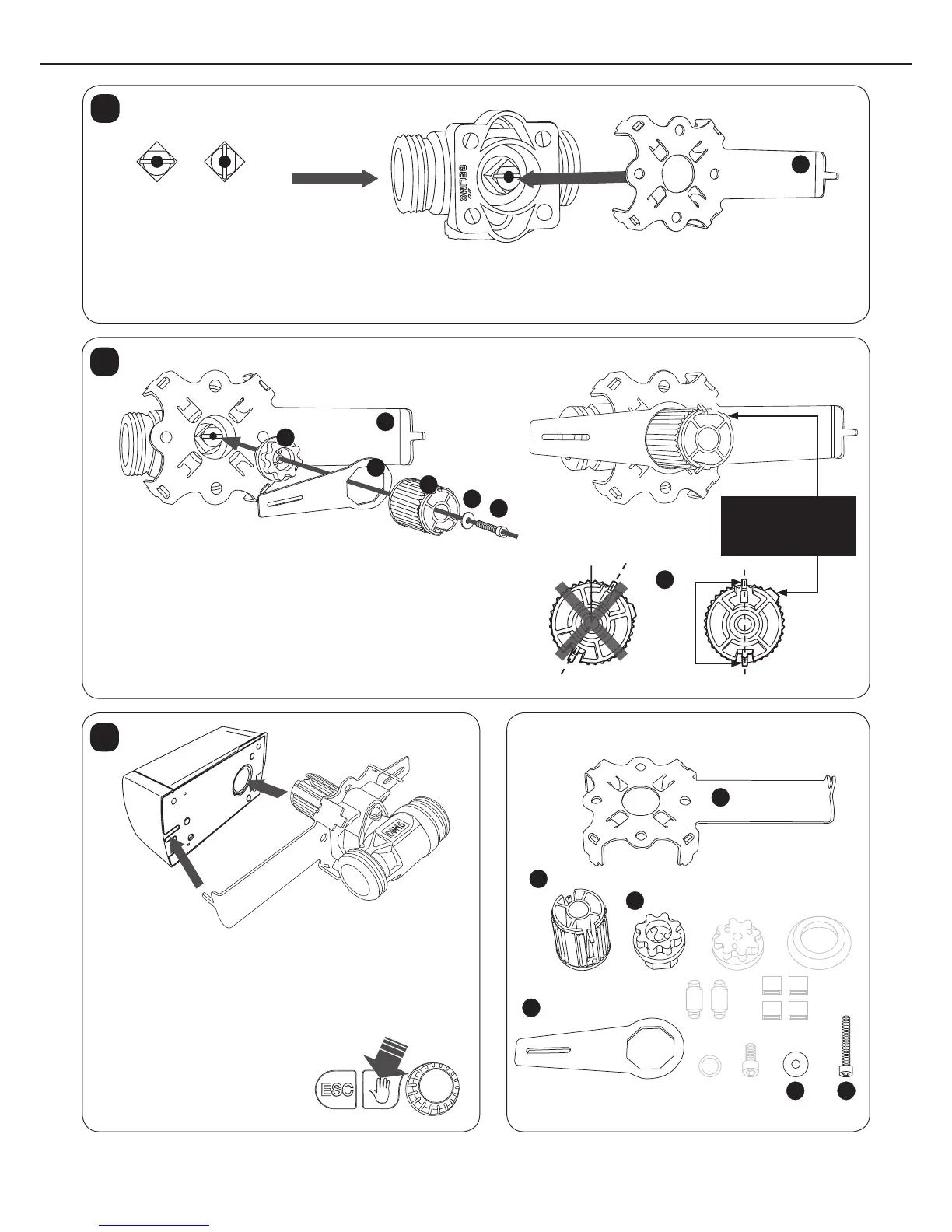
BELIMO BALL VALVE
Set the installation plate into the valve as indicated in the gure. The pegs located in the corners of the installation
plate should be aligned with the corner holes. Valve shaft should be open during installation. The regulator direction
of the valve opening counter-clockwise (1b) should be changed according to Section 12 (regulator installed).
Flow direction
A
AB
Open Closed
A
1
Install the shaft tting on the valve shaft while observing the shaft
bevel. Install the manual operation lever on the axle of the shaft t-
ting, pointing horizontally to the left (9 o’clock). Place the gear tting
to the shaft tting so that the manual operation lever is between the
ttings and the gear tting pinions point up and downwards.
The alignment surface of the tting should point towards 2
o’clock. Fix the parts to the valve shaft with the screw and washer.
2
D
A
B
C
D
E
F
NOTE!
The alignment surface
should point to this
direction.
Attach the regulator according to the illustrations, ensuring
that the gear tting alignment surfaces face the regulator
and the installation plate pegs are placed correctly.
Use the manual control lever to check that
the valve turns freely over the full range of
movement (90°). You must press the
manual control knob while you
are turning the manual control
lever.
3
D
B
C
E
F
А
Contents of the installation package
(Use only indicated parts!)
Installation
plate
Gear tting
Shaft tting
Manual operation
lever
ScrewWasher
Fitting pinions

 Loading...