4.3 DirectCableConnectionandPinout
The OS2 can be operated without the use of an Interface Box. In this case, a “pigtail” cable should
beusedandwiresshouldbeconnectedbytheuserfollowingthePinoutpresentedbelow. Whenused
withdirectcableconnection,thesensorshouldstillbeoperatedwithintheoperatingvoltagespecified
insection:ref: ‘PowerSupply andOperatingVoltage’
Warning: Ousterisnot responsibleforanyerrorsin wiringasa resultof bypassing theInterface
Box and this activity may result in a voiding your warranty if it results in damage to the sensor.
The following guidelines fordirect cable connection assume use of the Ouster-provided24V1.5A
powersupply. Oustercannotbe heldresponsiblefordamagetothe deviceifalternateisused.
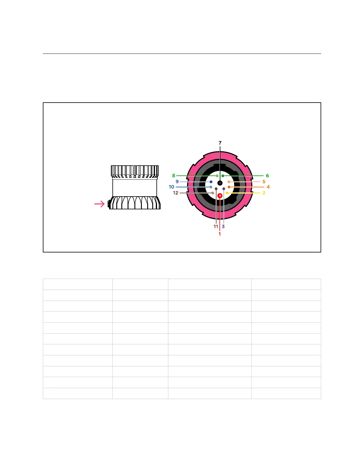
Figure4.1: cablepinoutof on-sensorreceptacle
Table4.1: Cablepinout wires
NetName PinNumber Wire TwistedWith
MULTIPURPOSE_IO 3 Purple,26AWG N/A
SYNC_PULSE_IN 2 Yellow,26AWG N/A
VCC_24 1 Red,22AWG N/A
GROUND 7 Black,22AWG N/A
TRP_1_P(Ethernet) 5 White/Orange,26AWG Orange
TRP_1_N(Ethernet) 4 Orange,26AWG White/Orange
TRP_2_P(Ethernet) 8 White/Green,26 AWG Green
TRP_2_N(Ethernet) 6 Green,26AWG White/Green
TRP_3_P(Ethernet) 9 Blue, 26AWG White/Blue
TRP_3_N(Ethernet) 10 White/Blue,26AWG Blue
continuesonnextpage
11