protection rating may be compromised. Bending the cable at a sharp angle directly after egress
fromtheplug overmold shouldalsobe avoided. Sharpbendsandhighaxialstressesonthecable
immediatelyadjacenttotheplugovermoldmaycreateamoistureingresspathintotheconnector.
Pleasenotethe cableminimumbend radiusrequirementsbelow:
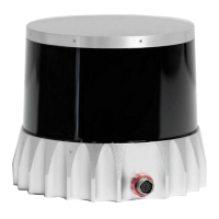
3.2 MountingGuidelines
Our sensors ship with modular mounting options. The sensor can be mounted in any orientation.
Propermountingwillensureoptimalsensorperformance,reducingnoisefromvibrationandproviding
efficientheat dissipation.
Mount toamaterialwith high thermal conductivity. The followingare recommendedaluminum
alloysandtheir thermalconductivity:
1) 6061: 167W/m-K
2) 7075: 130W/m-K
3) 2024: 121W/m-K
Ensureinterfacesareclean andfreefromdebris.
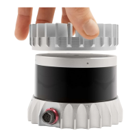
M3 screws are recommended formounting the sensor. The screw hole pattern in presented in
theSensordrawingaboveSensor Components.
Torque bolts appropriately for the mount material and bolts. A torque of 146cNm is recom-
mendedfora2stainlesssteelscrews.
UseTIM(ThermalInterfaceMaterial)foranyirregularor unmachinedsurfaces.
Donotoverconstrainthe sensorifmountingtoboththe topandthebottom.
Useathermallyconductivepadtoensuregood conductivitywhilenotoverconstraining.
Ensure your implementation maintains the base and top of the sensor at no greater than 25ºC
aboveambientwithanambientlessthan50ºC.
Theshapeofanyheatsinkshouldmaximizethesurfaceareaforfreeandforcedconvectionwhile
beingthickenoughtoallowtheheattoconductthroughthematerial.
If you have questions about your specific mounting situation please contact the Ouster at sup-
port@ouster.io.
9