Table 4.1 –continuedfromprevious page
NetName PinNumber Wire TwistedWith
TRP_4_P(Ethernet) 12 White/Brown,26AWG Brown
TRP_4_N(Ethernet) 11 Brown,26AWG White/Brown
5 DigitalIO
5.1 SYNC_PULSE_IN
SYNC_PULSE_IN isadedicatedinputchannelthatisaccessiblewithintheInterfaceBoxJumperJ4. This
channel expects an input pulse sequence which can be used for time synchronization. Refer to the
SoftwareUser Manual formore informationon configuring this input. Anyreferencesto pulse polar-
ity in this document references the signal polarity on the SYNC_PULSE_IN pin of the sensor. This input
channelisprotectedbyan opto-isolatorwhichwilldraw5mA atfulloperation.
Table5.1: SYNC_PULSE_INInterfaceRequirements
Parameter MinVoltage MaxVoltage MinDriverCurrent
LOGICLOW -30V 2V N/A
LOGICHIGH 2.9V 30V 3mA @3.3V~5V, 5mA
at24Vandhigher
SYNC_PULSE_IN Interface requirements were tested with 2 m cable Interface Box connection at 2
MHz.
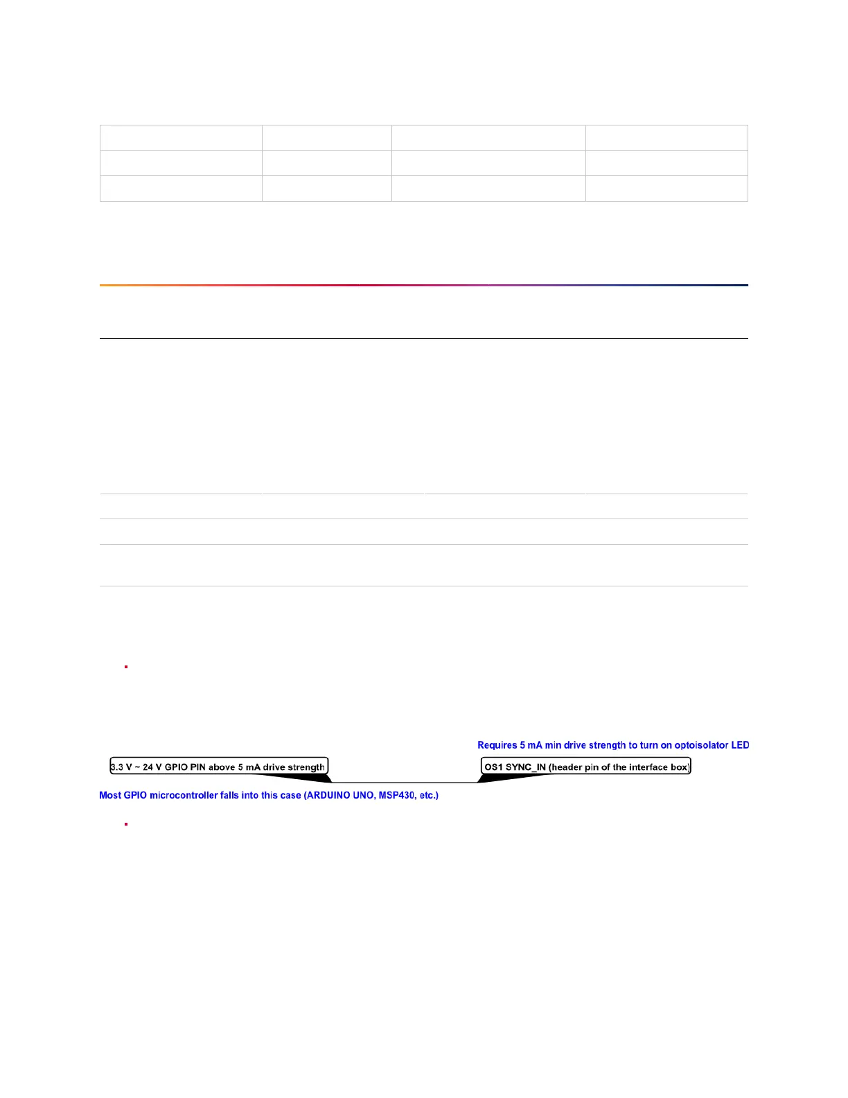
When GPIO has 5 mA drive strength minimum, GPIO can be directly connected to the
SYNC_PULSE_IN pinoftheInterfaceBoxheader. Thisisthemostcommoncaseandhasbeentested
to work on common Arduino microcontroller series. Typical common logic levels of 3.3 V, 5 V
GPIOofmicrocontrollerscanproducedrivestrengthof 5mAmin(Arduino,MSP430,etc.).
If the 5 mA drive strength minimum cannot be met, a buffer circuit is required to drive
SYNC_PULSE_IN.Examplecircuitsareprovidedforcommon3.3Vand 5Vlogic.
12