Do you have a question about the Outback Power Systems FX2024ET and is the answer not in the manual?
| Model | FX2024ET |
|---|---|
| Continuous Power | 2000 W |
| AC Input Frequency | 60 Hz |
| DC Output Voltage | 24 VDC |
| Output Frequency | 60 Hz |
| Battery Voltage | 24 VDC |
| Peak Efficiency | 93% |
| Efficiency | 90% |
| Operating Temperature | -20°C to 60°C |
| Weight | 25 lbs (11.3 kg) |
| Dimensions | 13.5 x 8.25 x 8 in (34.3 x 21 x 20.3 cm) |
Overview of OutBack Power Systems' role in energy conversion technology.
Copyright statement for the International FX and VFX Series Installation Manual.
Statement regarding the accuracy and use of information provided in the manual.
Company contact details for OutBack Power Systems.
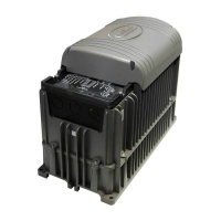
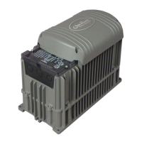
Guidance on inspecting the FX unit for shipping damage before installation.
Description of DC terminal connections and battery wiring.
How to manually control the inverter's power state via terminals.
Details on the 12VDC auxiliary output for fans or other loads.
Information regarding non-operational XCT+/XCT- terminals.
Details on AC Conduit Plate, FX-ACA, and DCA for wiring connections.
Information on the DCC and Turbo Fan Cover for unit protection.
Description and installation of battery terminal protective covers.
Step-by-step guide for connecting AC power.
Guidelines for connecting DC power from batteries.
Example of a series connection of 6V batteries for a 12V FX system.
Example of series/parallel 6V battery connection for a 12V FX system.
Example of a series connection of 12V batteries for a 24V FX system.
Example of a parallel connection of 12V batteries for a 12V FX system.
Notes on connecting the AC hot output conductors.
Notes on connecting AC neutral conductors.
Notes on connecting the AC hot input conductor.
Methods for manually switching the inverter on and off using terminals.
Details on the 12VDC auxiliary output for cooling fans or other tasks.
Note that XCT+/XCT- terminals are not operational.
Explanation of LED indicator colors and their meanings.
List of potential warning screens and error conditions.
Diagram for installing a single FX unit in a system.
Specific wiring diagram for connecting a two-wire start generator.
Specific performance and electrical ratings for FX2012ET and FX2024ET.
Specific performance and electrical ratings for FX2348ET and VFX2612E.
Information on nominal AC output voltage and maximum DC load current.
Guidance on the recommended DC input voltage range for FX systems.
Specific performance and electrical ratings for VFX3024E and VFX3048E.
Maximum continuous DC current for battery charging.
Operating voltage range and maximum input current for FX units.
Information on the maximum current for the battery charger function.
Table of maximum AC input and DC charger output values.
Details on maximum AC output current and continuous output power.
Specified AC input frequency range for FX models.
Steps for safe, user-level maintenance of the FX.
Default, min, and max values for 12 VDC system configurations.
Default, min, and max values for grid and generator input settings.
List of conditions that void the product warranty.
Steps to follow for obtaining warranty repair or replacement.
Statements disclaiming other warranties and limiting liability.
Fields for system owner and product model/serial number information.
Fields for system installation details and installer contact information.
Information on purchasing an optional extended warranty.
Address and phone number for the main OutBack Power Systems office.
Address and phone number for the European sales office.