Do you have a question about the Outback Power Systems MATE and is the answer not in the manual?
Lists key features and specifications of the MATE unit, including display, keypad, indicators, and connectivity.
Details the installation process, including mounting, cabling, and PC interface connection.
Explains the MATE's power-up sequence and initial display screens, including version information.
Describes how to navigate through the MATE's menu system using its buttons and soft keys.
Introduces commonly displayed screens like Main, Summary, and Status screens.
Explains how to connect and use the MATE with a HUB communication manager for multiple devices.
Instructions for setting the internal clock of the MATE controller.
Details how to adjust the contrast of the MATE's LCD display for better readability.
Instructions for adjusting the backlight brightness of the MATE's LCD display.
Explains how to configure options for the summary screens displayed by the MATE.
Details the settings for MATE communications options.
Describes the High Battery Transfer (HBX) mode for the MATE.
Details the settings and configuration for the Grid-Use mode.
Covers the setup and operation of the Advanced Generator Start mode.
Provides an overview of the MATE's menu structure and navigation.
The OutBack MATE is a comprehensive system controller and display designed for use with OutBack FX inverter/chargers and MX60 PV MPPT charge controllers. Its primary function is to provide a visual interface for monitoring system operation and to allow users to control and adjust product setpoints. Beyond individual device control, the MATE also plays a crucial role in coordinating the entire system, ensuring optimal performance and preventing conflicts between multiple connected products.
One of the key features of the OutBack MATE is its ability to connect to multiple OutBack products through a communication manager called a HUB. This HUB can be either a HUB-4, supporting up to four products, or a HUB-10, which can manage a maximum of ten OutBack devices. This multi-device connectivity allows a single MATE to oversee and manage a complex power system, including multiple FX inverter/chargers and MX60 PV MPPT charge controllers, as well as any future OutBack products. The connection between the MATE and the HUB, and between the HUB and the individual products, is made using standard CAT 5 type Ethernet cabling with 8-wire RJ45 modular connectors. This standardized cabling makes installation and expansion relatively straightforward.
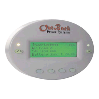
The MATE's user interface is built around a four-line, 80-character backlit LCD display, capable of showing both alphanumeric and graphic information. This display is complemented by a control keypad featuring six backlit silicone membrane keys. Among these, two are dedicated "hot" keys: "INV" for inverter control and "AC IN" for AC input control. These hot keys are designed for quick access to frequently used functions, allowing users to control essential aspects of their system from any point within the MATE's menu structure. The remaining four keys are "soft" keys, whose functions change dynamically based on the labels displayed directly above them on the LCD. This context-sensitive design allows for a versatile and adaptable control scheme.
Status indicators are also integrated into the MATE, providing immediate visual feedback on system operation. A green LED indicates inverter status, flashing when the inverter is in search or power save modes, and remaining continuously on when full AC output voltage is available. A yellow LED indicates AC input status, flashing when an AC source is available but not connected, and staying on continuously when the AC source is connected and in use. These LEDs offer a quick glance at the system's operational state.
The MATE employs a proprietary OutBack Multi-drop network for communication, utilizing the OutBack HUB. The interconnecting cable is a standard CAT 5 PC network cable, wired as non-crossover, with RJ45 modular connectors. This cable can extend up to 1000 feet, although signal degradation can occur in "noisy" environments, such as when the cable is run in conduit with AC wiring. For advanced users and system integrators, the MATE also includes an RS232 Opto-Isolated DB9 serial communication port, enabling connection to a PC for further monitoring or configuration.
Installation of the MATE is designed for surface mounting in an indoor location, away from direct sunlight to ensure display visibility. The device is shipped with a 50-foot cable, but longer or shorter pre-made cables can be purchased, or custom lengths can be made on site. The MATE's back cover can be unsnapped to reveal mounting holes, allowing it to be securely attached to a wall. The RS-232 port is conveniently accessible from the bottom when wall-mounted, or the unit can be removed for easier serial cable connection.
Upon power-up, the MATE undergoes a self-initialization process, displaying a series of information screens. These include a greeting, copyright information, and screens showing the MATE's code and screen revisions. These version numbers are important for troubleshooting and support. Following this, the MATE searches for and displays connected devices, indicating whether an FX inverter or MX charge controller has been found. If no devices are found, users are directed to a troubleshooting section.
The MATE's menu system is hierarchical, allowing users to navigate through various operational modes and status displays. The main screen serves as the root, or home screen, from which all other menus branch. Users can quickly return to the main screen by simultaneously pressing the two left soft keys or by selecting a soft key labeled "
The "soft" keys are central to navigation and setting changes. Labels like "
The "INV" hot key provides direct control over the inverter, allowing users to turn all connected inverters off, activate search mode (for low AC loads), or turn them all on. The "AC IN" hot key offers similar direct control over the AC input, enabling the inverter to connect to an available AC source ("USE") or disconnect from it ("DROP"), while still allowing reconnection if the battery is low or the inverter is overloaded. Repeated presses of the "AC IN" key cycle through additional control screens, including "GEN START CONTROL" for managing advanced generator start modes, "CHARGER CONTROL" for presetting battery charger operation, and "CHARGER MODE CONTROL" for issuing global charger commands like bulk charging or equalization.
Summary screens provide an overview of the current status of all connected OutBack products. These can be accessed from the Main screen via the "
Status screens, accessible via the "
For more advanced configurations, the MATE includes "Advanced Screens," which are password-protected to prevent unintended changes that could adversely affect system operation. These menus allow users to set initial system parameters for FX, MX, and MATE products, covering categories like inverter setup, charger setpoints, grid input setpoints, generator input setpoints, auxiliary output settings, stacking setup, grid-tie setup, and meter calibrations. The MX Advanced menus specifically focus on the MX60s AUX output. MATE Advanced menus include settings for high battery transfer (HBX), time of day grid usage (GRIDUSE), and advanced generator starting (AGS). These advanced settings are crucial for tailoring the system to specific operational requirements and are detailed in a dedicated section on MATE Control Modes.
Maintenance features are primarily focused on ensuring proper communication and device recognition. If a new device is added to a HUB or an existing device is moved, the MATE must be either unplugged and re-plugged into the HUB or a "REPOLL" command must be used to force the MATE to rediscover all devices. This ensures that the MATE accurately reflects the current system configuration. The manual also emphasizes the importance of checking the website for the latest product information and firmware revisions, as these can impact the MATE's functionality and available features. Troubleshooting sections are provided to assist users if devices are not found or commands fail to function as expected.
| Display Type | LCD |
|---|---|
| Data Logging | Yes |
| Enclosure Type | Plastic |
| Communication Ports | RS232 |
| Compatibility | Outback Power Systems Inverters and Charge Controllers |
| Remote Monitoring | Yes |
| Mounting | Wall Mount |