Outlaw Audio
6
precautions on page 2).
Connecting
Your Amplier
When making connections between
any source components and the Model 5000,
or when making connections to any speaker,
be certain that both the input devices and the
amplier are turned o. To assure that there
will be no unwanted signal transients that can
damage equipment or speakers, it is always
best to unplug all equipment before making any
connections. Modern electronic products often
have a standby mode that may be activated
even though the product may appear to be
turned o.
To connect the amplier to your speakers a pair of binding
posts is provided for each channel output. These posts will
accept bare wire, spade lugs, or banana type plugs (when
permitted by local safety agencies.)
Be sure to maintain the correct polarity between your
amplier and speakers for proper phasing. When speaker
phasing is correct, all speakers move in and out at the same
time, preserving the imaging of the program material.
Out-of-phase connections will result in some speaker cones
moving in while others move out, causing indistinct or
confused imaging, and muddled, cloudy sounds. To avoid
incorrect phasing or polarity, be certain to use cable that
has distinct markings, colors, stripes, wording, or grooves
on each side of the speaker cable.
When making connections to the amplier and speakers,
adhere to a consistent pattern of using one side of the
wire to the red terminals and the other side to the black
terminals. If you are using speaker cable with markings on
one side only, convention is to consider the marked side
of the wire as the red, or positive (+) connection, and the
non-marked side as the black or negative (-) connection.
Overview
Before you Begin
To assure that the signals received and produced by your
Outlaw amplier are carried to your speakers without loss
of clarity or resolution, we recommend that you use high-
quality audio interconnect cables and speaker wire. There
are many brands available. The choice may be inuenced
by the distance between your source device, amplier and
speakers, the type of speakers you use, personal prefer-
ences, or other factors.
Regardless of the brand or type of speaker wire selected,
we recommend that you use a wire constructed of ne,
multi-stranded copper with a gauge of 14 or less. Remem-
ber that in specifying wire, the lower the number, the
thicker the cable. Wire with a gauge of 16 may be used for
short runs of less than ten feet. We do not recommend that
you use any wires with an AWG equivalent of 18 or higher
due to the power loss and degradation in performance that
will occur. tions
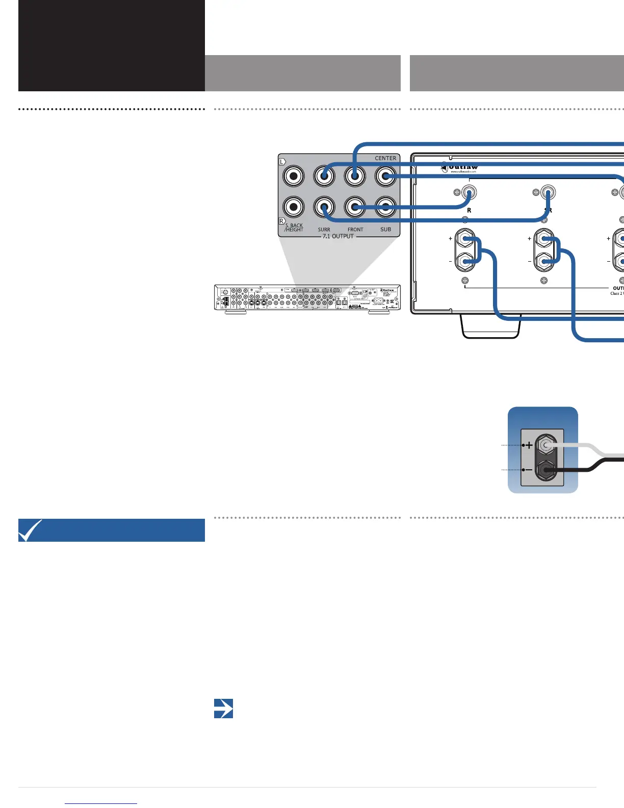
Input Connections
Connecting the amplier to your source equipment is
simple. Using high-quality audio interconnect cables,
match the output channel designations on the rear of your
processor (or other source equipment) to the input jacks
on the rear panel of the Model 5000 that have the same
channel name.
When making connections with RCA type plugs on inter-
connect cables, make certain to gently, but rmly insert
the plug into the jack. Never twist the RCA plug when
plugging or unplugging. Loose connections can cause
intermittent sound and may damage your speakers. The
barrel assembly of some high quality RCA plugs may be
very tight, and it is important to assure a proper connec-
tion between the interconnection cable and the input jack.
IMPORTANT NOTE: Before attempting to plug/unplug
any input jacks into/from any power amplier, verify that
the power amplier is turned o and/or disconnected from the AC
power. Failure to do so can potentially result in severe damage to
your amplier and loudspeakers.
Speaker Connections
Model 5000 Input Connections Model 5000 Speaker Connections
Model 5000
Model 5000
Outlaw Audio LLC
Easton MA USA
Designed in the USA by Outlaw Audio and manufactured in the P.R. China
Positive terminal post is colored
red and labeled with the plus sign (+)
Negative terminal post is colored
black and labeled with the
minus sign (–)