5
S-176-9-E
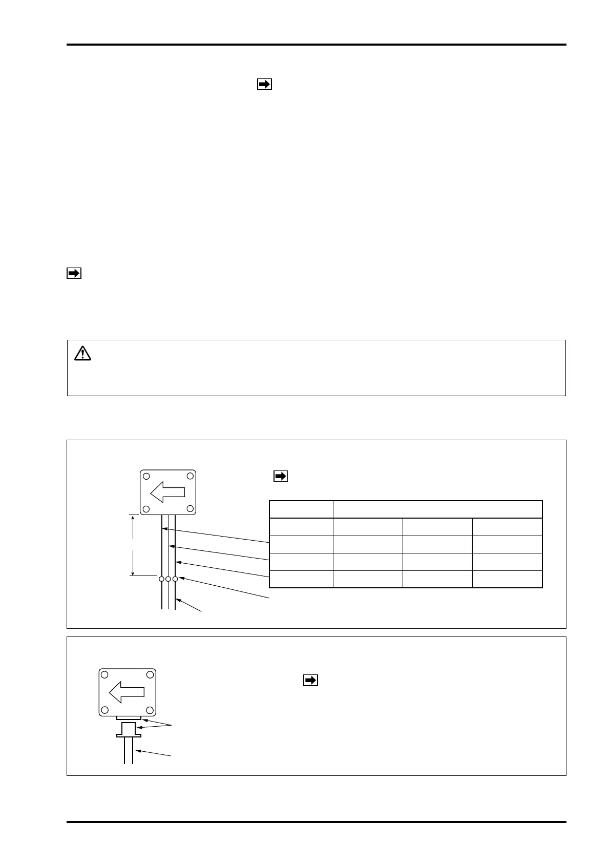
Soldered or coupled with connector.
Unfactored pulse
Factored pulse
All models
※
Size 40 (1mL/p) Size 41 (1mL/p) Size 45 (10mL/p)
WHT: SIG GRN: SIG YEL: SIG GRN: SIG
RED: +V RED: +V RED: +V RED: +V
BLK: 0V BLK: 0V BLK: 0V BLK: 0V
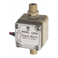
Wire leads (customer to furnish)
Connector and Receptacle
Wire leads (customer to furnish)
◆
3-Wire System (MR sensor): Meter sizes 38, 39, 40, 4
1, and 45
NOTE
※
: Unfactored pulses only with Meter sizes
38 and 39 .
◆
2
-Wire
System (reed switch): Meter sizes 40, 4
1, and 45 (unfactored pulses only)
NOTE: 1. Remove connector terminals and crimp
wire leads for installation.
2. The sensor is of reed switch type.
Polarity observation is not required.
4. WIRING
4.1 Field Wiring
(1)Cables for eld wiring
The following cables should be used unless otherwise specied.
Shielded chloroprene cabtyre cables (kind 2, JIS C 3327, shielded) or shielded vinyl cabtyre
cables (JIS C 3312, shielded) with a conductor area 1.25mm
2
.
3-conductor cables may be used to suit your specic application. Shielded end should be
grounded
a
t the ground terminal of the receiving instrument.
(2)Transmission length
With transmission cables conforming to JIS C 3327 or C 3312 conductor area 1.25mm
2
, the
maximum transmission length is typically one kilometer.
NOTE:
If
it exceeds one kilometer, consult factory.
(3)Prevention of inductive interference
T
o minimize the possibility of stray current pickup, route the eld wiring sufciently away from other
power cables and power circuits.
CAUTION: Verify the validity of flowmeter (pulse generator) to receiving instrument
combination by their product No., instrument No., etc. before making wiring
connections.
NOTE : Also see the topic "WIRING" in the instruction
manual of the receiving instrument used.
4.2 Electrical Connections