T-518-11-E
2
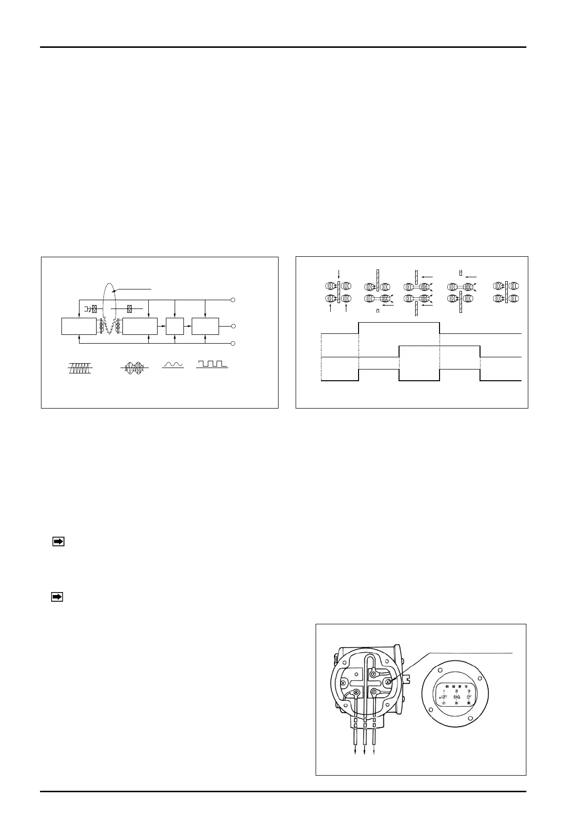
Receivecoil
Sendcoil
Waveform
Tootheddisk
HF
Oscillator
Detector
Recti-
fier
Wave-
shape
L
1
L
2
① ② ③ ④
(BLK)
(WHT)
Power+12V
OutputSIG
Power0V
(RED)
Send
coil
Receive
coil
V1
V1
V2
Output
(Output =V1XORV2)
Tootheddisk
V1
V2 V2
Fig. 1
Fig. 2
■
WIRING INSTRUCTIONS
1. Cables for eld wiring
Recommended cables for field wiring are 3-conductor, shielded, chloroprene cabtyre cables [kind 2] (JIS C
3311) or 2-conductor, shielded, vinyl cabtyre cables (JIS C 3312) 1.25mm
2
to 2.0mm
2
in conductor area unless
otherwise specified.
2. Transmission Length
The maximum Transmission length is one kilometer when cables 2mm
2
in conductor area conforming to JIS C
3311 or C3312 are used.
NOTE: If it exceeds one kilometer, consult the factory.
3. Conduit work is suggested.
Cable connections: PG30 ……Rc (PT) 3/4 female
PG30EP…G (PF) 3/4 female
NOTE: With conduit, a minimum of five full threads should engage the mating thread.
Wiring connections
Remove the lid of PG30/PG30EP housing to gain access to
a 3-post terminal block. Terminal identification label is found
on the reverse side of the lid. Remove a wiring connection
instruction label put on the terminals.
1 → +12V WHT
Terminal No. 2 → SIG RED
3 → 0V BLK
If grounding at the pulse generator end is desired
With PG30EP, use the earth ground terminal furnished.
With PG30, no ground terminal is provided; take off a screw
as shown in Fig 3 and earth ground using a terminal lug.
■
OPERATING PRINCIPLE
1. Operation can best be understood by referring to Fig.1. Oscillator coil L
1
in the HF oscillator continuously
generates a 1MHz high frequency wave (waveform ① ). As a toothed disk, located between the coil and
detector rotates, a high frequency induction field created is intermittently interrupted. The resultant signal
induced in pickup coil L
2
of detector is a wave modulated by the toothed disk (waveform ② ). The signal is
then detected(waveform ③ ) and further shaped into a rectangular signal (waveform ④ ).
Hysteresis characteristics are also provided electrically by changing trigger levels at the leading edge and
trailing edge of the signal.
2. Fig.2 shows how our proprietary double pulse generator works. With two pairs of HF send/receive coils
arranged opposite to each other, intermittent interruption of the magnetic field takes place by the rotating
toothed disk and causes each coil to produce a single pulse per gap (or slot) between the teeth.
Because two coils are so located as to produce pulses 90°out of phase from each other, by exclusive OR (XOR)
of pulses from these two coils, two pulses per gap between the teeth are obtained after all.
Ground this terminal if
required.
Fig. 3