4. Conduit work for Model PG30EP (ameproof type)
(1) Use steel conduit conforming to the requirements specified in JIS C 8305.
(2) Conduit accessories should be of flameproof rating.
(3) Sealing work should be taken into consideration.
(4) Where rusting the screw threads is anticipated, apply a coat of non-drying sealing compound externally
following the screw engagement of conduit.
5. Inductive Interference Prevention
Field wiring should be routed sufficiently away from existing power cables or power circuits, if any, to prevent
potential stray current pickup.
If you want to use both scaled unit pulses and unscaled pulses, use two separate cables.
T-518-11-E
3
23
1
SIG0V
MODEL
PG30, PG30EP
12VDC
+12V
10k
Ω
a
+
b
103 102
116
119
139
Fig. 5Fig. 4
167
Transmission gear box
PG30 PG30
Fig. 7Fig. 6
Shown in Fig.6 above is the setup for observing the
output pulse waveform. Couple the oscilloscope
across terminals a and b and monitor the waveform
while allowing the pulse generator to rotate at a
constant rpm. Connecting the voltmeter across
terminals a and b enables you to make an ON/OFF
level measurement. However, you cannot make a
pulse ON/OFF ratio (or duty factor) measurement with
voltmeter alone.
Correct ON/OFF ratio C/D ranges from 35/65 to 60/40
when "1"= 6.2 to 7.6V and "0"= 0.5 max.
If a correct waveform like the one shown in Fig.7 is
not obtainable, replace the noncontact switch unit with
a new one according to the procedure outlined in the
next section.
(The ON/OFF ratio is a value measured under steady
state rotation.)
■
DISASSEMBLY AND INSPECTION
◎
The pulse generator should be disassembled for inspection once a year.
(Make sure that the transmitter cables are not lodged between the casing parts while reassembling.)
If there is no or few (or too many) pulses from the pulse generator while the flowmeter register pointer moves or
the counter operates properly, trouble is suspected in the pulse generator. Inspect its components according to
the procedure described below.
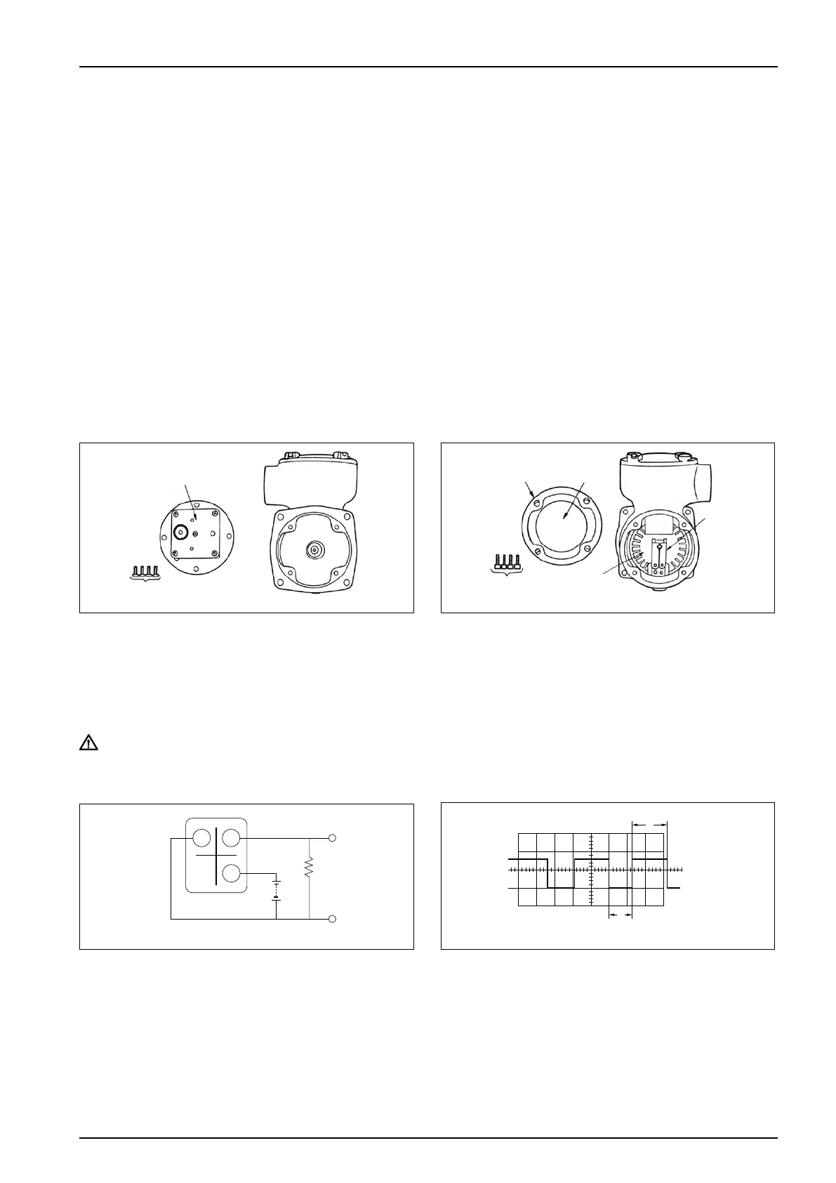
1. Remove the pulse generator from the flowmeter.
Take off four screws (167) to gain access to the
transmission gear box. Check for any gear slipping
on its shaft or crimp connections that are loose.
The same procedure applies to Model PG30EP.
CAUTION: If something is wrong with spring (122) and/or brake shoe (119), replace the whole brake
shoe assembly (plate (120) inclusive).
●
Monitoring the Output Waveform
2. Take off four screws (139) holding the housing lid
(102) in place and remove the lid.
Check to see that toothed disk (116) turns smoothly
and that the brake shoe (119) works properly.