T-518-11-E
4
109
108
110
111
126
118 115
Terminal box
117
PG30 PG30EP
※
116
※
Gear Train Bearings
Brake Shoe
Spur Bevel Plain Ball
G2 G2 L3 L3 L3
Symbol Viscosity or Consistency Pour Point or Drop Point Example of Products by Trade Name
L3 36.4
cst
/30℃ − 37.5℃
Nisseki Launa 40
(Nippon Oil Co., Ltd.)
G2 300/25℃ 300℃ and above
Jun BG Grease
(Nihon Tokushu-koyu Co., Ltd.)
●
Lubricating Oil Specications and Examples of Products
■
LUBRICATION
Do not fail to use proper lubricants shown below, or equivalent, at disassembly and inspection.
L: Lubricating oil
G: Grease
●
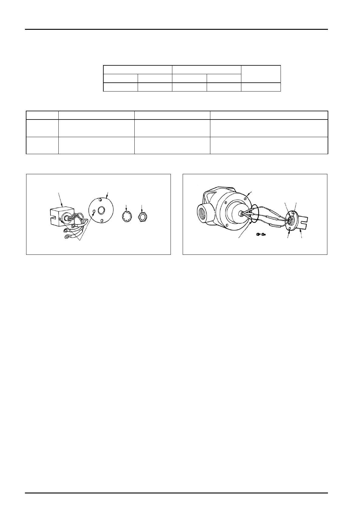
Noncontact Switch Unit Replacement
Fig. 9
Fig. 8
1. Disconnect wiring connections. Take off two
terminal fitting screws (106) and remove terminals
(104). The noncontact switch unit (108) can be
separated by taking off two additional screws (130).
2. Remove nut (110) and toothed washer (109)
holding the noncontact switch unit (108) to
mounting bracket (111), and remove the switch
unit. Install a new switch unit in alignment with
locating slot (marked ※ ). Ensure correct wiring
connections with due regard to color coded leads
(white, red and black).
1. Take off four bolts (329) and remove the casing
of pressure-resistant gasket (301) from housing
(101). Then, take off two screws (126) securing the
noncontact switch unit (115) in place and remove
the switch unit.
2. Unsolder wire lead connections (marked ※ ), take
off nut (117) and toothed washer (116) holding the
noncontact switch unit (115) to mounting bracket
(118), and separate the switch unit.
Replace with a new noncontact switch unit in the
same manner as described for PG30 pulse generator
and solder wire leads to their connections.