"Hydrocontrol MTR" (lead-free) Installation & Initial Operation
19
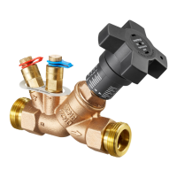
Fig. 12:
Marking valve with colored ring
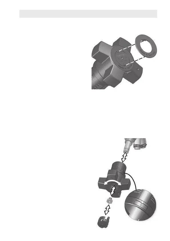
Fig. 13:
Pulling off and repositioning handwheel
1
2
3
4
5
Marking Feed/Return
Usea colored ring tomark the
valveashavingbeeninstalledin
a feed line (red) or a return line
(blue).Thetwotabsofthecolo-
red ring are used to attach it to
thehandwheel(Fig.12).
If peripheral scale is hard to
read: Reposition handwheel
Depending on the installation po-
sitionofthevalve,itmaynotbe
possible to read the peripheral
scaleforthenesetting.Ifthisis
the case, you can reposition the
handwheel to bring the display
intothelineofsight.
1. Setbothscalesto"0"
(valveclosed).
2. Removecoverplug(5).
3. Undoscrew(4)withsocket
wrench(12mm).
4. Pullhandwheel(2) off of valve
spindle
(1)
withslighttug.
5. Turnhandwheel
(2)
so that
window of peripheral scale
(3)iseasilyvisible.Do not
change "0" setting when
doing so.
6. Sethandwheelontovalve
spindleandreplacescrew.
7. Pressoncoverplug.