ThunderBay Flex 8
Introduction
3
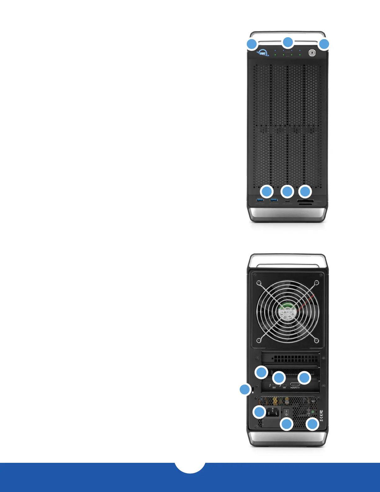
1.4 Front View
1. Power LED – When powered on without a data connection
will display white. When powered on with a data connection,
will display blue.
2. Drive Status LEDs – The top row displays the status of SATA
and/or U.2 Drives, while the bottom row displays the status
of additional SATA drives. The LEDs on the top row will ash
blue for U.2 drive activity or green for SATA drive activity. The
bottom row will ash green for SATA drive activity.
3. Security lock – secure installed drives by using this lock.
4. USB 3.2 Gen 2 ports – connect compatible USB devices with
a Type-A connection here.
5. USB 3.2 Gen 2 port – connect a compatible USB device with
a Type-C connection here.
6. Media cards – use the top slot for CFexpress Type B card;
use the bottom slot for SD-compatible media (up to SD 4.0).
1.5 Rear View
1. PCIe slot cover – any available I/O ports on installed PCIe
cards will be available here.
2. Thunderbolt 3 ports – connect a compatible host to the
85W port and chain additional Thunderbolt 3 devices to
the 15W port.
3. DisplayPort 1.4 – connect a DisplayPort display here.
4. Security slot – connect a security tether here.
5. Power input – connect power cable here.
6. Power switch – power the device on or off with this switch.
7. Power light – additional power indicator.
1
4
1
2
4
5
6 7
3
5 6
2
3