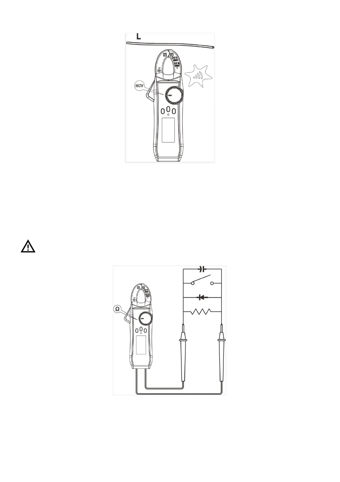
Figure 6
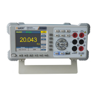
4. Resistance / Circuit ON/OFF/ Diode/ Capacitance
Select resistance/ continuity /capacitance/diode function.
Insert the red probe into the red hole (positive pole) and the black probe into the black hole
(COM terminal).
Connect the probes to the tested part for measurement (Figure 7)
Read the measured data from the LCD screen.
When the instrument is switched to resistance/ continuity /capacitance/diode function, the
input voltage cannot be higher than 60V (DC) or 30V (AC) to guarantee personal safety.
Figure 7
5.
Measurement of Frequency and Duty Cycle
Select frequency/duty cycle function.
Insert the red probe into the red hole (positive pole) and the black probe into the black hole