3. Clamp head trigger: Press the trigger to open the clamp head.
4. ZERO button: It is used for making DCA to zero, relative capacitance/voltage
measurement/ press and hold the button for about 2 seconds to enable/ disable Bluetooth.
5. HOLD/ Backlight Button: It is used for locking measured reading / press and hold the button
for about 2 seconds to enable/ disable backlight.
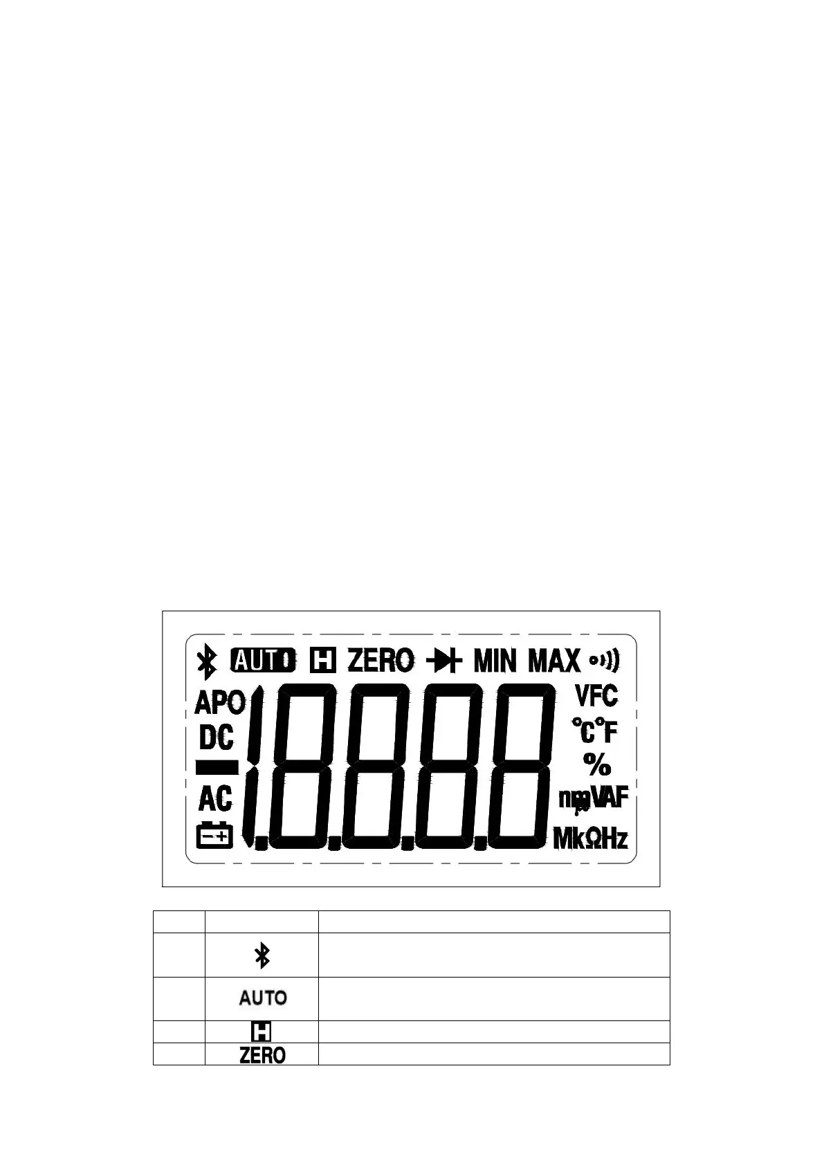
6. LCD display: Displays measurement function, symbols and values.
7. COM input jack: The black probe is inserted this jack when this product is used to test
voltage, resistance/ continuity /capacitance/diode, frequency/duty cycle.
8. Positive end input jack: The red probe is inserted this jack when this product is used to test
voltage, resistance/ continuity /capacitance/diode, frequency/duty cycle.
9. NCV and alarm indicator: It will flash when the induced AC electric field strength and
sensing distance meet the specified value or the measurement of other gear exceeds the
range.
10.SELECT button: Used to select the functions, such as ACV/DCV, resistance/ continuity
/capacitance/diode, ACA/DCA, frequency/duty cycle, etc. when AC current and voltage
function is selected, if you press and hold this button for 2 seconds to enter or exit the VFC
function.
11.Function Selection knob: Rotate this knob to switch over the corresponding function
indicated on the panel.
12.The geometric center indication mark of the clamp head.
13.NCV induction antenna.
V. LCD Full-Display Diagram
Figure 2
Enable reading holding mode