Do you have a question about the Owon PC341-W-TY and is the answer not in the manual?
Essential safety guidelines to prevent hazards like fire, electric shock, and property damage.
Details on Wi-Fi standards and RF characteristics of the device.
Key physical and operational parameters including voltage, systems, accuracy, and dimensions.
Overview of the power meter's capabilities, including Tuya compliance and monitoring functions.
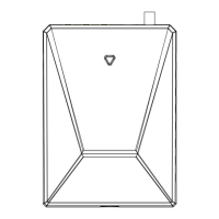
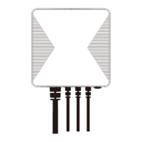
Identifies the main unit and its associated accessories like CTs, antenna, and power cable.
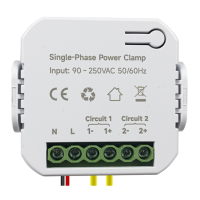
Details the location and function of device ports and the reset button.
Explains reset functionality and LED status meanings for device monitoring.
Critical safety warnings for qualified personnel during installation to prevent injury.
Steps for turning off power and selecting a suitable mounting location for the meter.
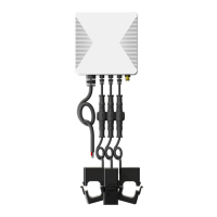
Guidance on installing the external antenna and clamping Main CTs around service lines.
Instructions for clamping Main CTs on service lines, including specific cases like solar connections.
Steps for connecting Main CTs to the power meter and connecting the power cable.
Detailed wiring instructions for Single-Phase, 3-Phase, and Split-Phase systems.
Instructions for clamping Sub CTs around individual circuits for monitoring.
Steps for connecting Sub CTs to the power meter and noting circuit jack assignments.
Visual guide for 3-phase wiring configurations in homes and commercial systems.
Diagram illustrating split-phase wiring for monitoring home loads.
Diagram illustrating split-phase wiring for monitoring solar energy production.
Visual guide for single-phase wiring configurations in European homes.
Instructions on how to download and install the required Smart Life mobile application.
Describes two methods for network configuration: QR scan and Bluetooth pairing.
Steps for adding the device to the app and connecting it to the Wi-Fi network.
Guide on how to attach the mounting bracket to a Din-Rail for secure installation.
This document outlines the features, safety guidelines, installation process, and network configuration for the PC341-W-TY Multi-Circuit Power Meter. This device is designed to help users monitor electricity consumption and production in their facilities by connecting clamp-on current transformers (CTs) to power cables.
The PC341-W-TY Multi-Circuit Power Meter is a smart energy monitoring device that provides real-time and historical data on electricity usage and generation. It is compliant with the Tuya smart home platform, allowing for automation and integration with other Tuya-compatible devices. The meter supports various electricity systems, including Single, Split-Phase 120/240VAC, and 3-Phase/4-wire 480Y/277VAC (without Delta/wye/Y/Star Connection).
The device offers comprehensive monitoring capabilities, enabling users to remotely track whole-home energy consumption and production. Additionally, it can monitor up to two individual circuits using 50A Sub CTs, which can be used for specific loads like solar panels, lighting circuits, or receptacles. The meter supports bi-directional measurement, meaning it can track both energy consumed from the grid and energy produced (e.g., from solar panels) and fed back into the grid.
Key real-time measurements provided by the PC341-W-TY include Voltage, Current, Power Factor, Active Power, and Frequency. This detailed data allows users to gain a deep understanding of their electrical system's performance and identify areas for energy optimization. All collected energy data, both consumed and produced, is stored as historical data, enabling users to review trends and make informed decisions about their energy usage over time.
The PC341-W-TY Power Meter is designed for ease of use, from initial setup to daily monitoring. The device integrates with the Smart Life application, which can be downloaded from app stores or via a QR code provided in the manual. This application serves as the central interface for configuring the device, viewing data, and managing automation rules.
Network configuration can be done through two methods. Method 1 involves opening the Smart Life app and using the 'Scan' button to scan a QR code, which will guide the user through the network setup process. Method 2 leverages Bluetooth for a more streamlined setup. Users power on the device, ensure the LED indicator is flashing green (resetting if necessary), and then open the Smart Life app with Bluetooth enabled on their phone. The app will automatically detect nearby devices, or users can manually add the device by clicking the '+' button. Once detected, users enter their home Wi-Fi credentials (note: 5GHz Wi-Fi is not supported) to connect the meter to the network.
Once connected, the Smart Life app provides an intuitive interface for monitoring energy data. Users can view real-time metrics and access historical data for both overall home energy and individual circuits. For circuits that generate energy, such as those connected to inverters, the app allows users to manually set the phase of the circuit in the settings to ensure accurate power measurements.
The device's LED indicator provides clear status updates: a blinking green LED signifies that the device is waiting for pairing, a solid green LED indicates a successful connection to the cloud, a solid red LED means the device is connected to the router but failed to connect to the cloud, and a blinking red LED indicates that Wi-Fi has been configured but failed to connect to the router. These visual cues help users quickly diagnose connection issues.
The mounting bracket included with the PC341-W-TY supports Din-Rail installation, providing flexibility for placement within or outside the electrical panel. The bracket features three hooks that securely attach to the Din-Rail, and the meter itself then hooks into the mounting bracket. This design ensures a stable and organized installation.
The PC341-W-TY Multi-Circuit Power Meter is designed for reliable operation, but proper installation and occasional checks are important for its longevity and accuracy. The manual emphasizes that the Power Meter must be installed and serviced only by qualified electrical personnel to ensure safety and proper functioning. Users are explicitly warned not to touch the terminals of the device during testing and to always confirm that the power supply is off using a properly rated voltage sensing device before connecting or disconnecting any auxiliary devices. All devices, doors, and covers must be replaced before reapplying power to the equipment. Failure to follow these safety instructions can result in serious injury or death.
The device includes a reset button that serves a crucial maintenance function. Pressing and holding the reset button for 5 seconds will cause the LED indicator to flash red three times quickly, restoring the Power Meter to its default factory settings. It's important to note that this action will not clear energy data. If a user wishes to clear the energy data, they must delete the device from the Smart Life app and wipe the data through the app before adding the device again. This distinction allows users to troubleshoot connection issues without losing their valuable historical energy records.
The external antenna, which has a magnetic base, should be located outside the electrical panel to prevent signal blockage by metal. This ensures optimal wireless connectivity for the device. If the Power Meter is installed inside the electrical panel, a knockout cover can be used to feed the external antenna cable through, maintaining signal integrity.
The current transformers (CTs) are designed with clear directional indicators (arrows P1→P2 or K→L) on their clasps or stickers. During installation, it is critical to ensure that the Main CTs point towards the breakers and the Sub CTs point towards the load or inverter. Incorrect orientation can lead to inaccurate measurements. For circuits that generate energy, such as those connected to inverters, the app allows for manual phase setting after wiring is complete. This ensures that the power measurement is correct, highlighting the importance of app-based configuration for specific scenarios.
| Model | PC341-W-TY |
|---|---|
| Brand | Owon |
| Display Type | LCD |
| Diode Test | Yes |
| Continuity Test | Yes |
| Type | Digital Multimeter |
| Connectivity | USB |
| Measurement Functions | AC Voltage, DC Voltage, AC Current, DC Current, Resistance, Capacitance, Frequency, Temperature, Diode Test, Continuity Test |
| Safety Rating | CAT III 600V |