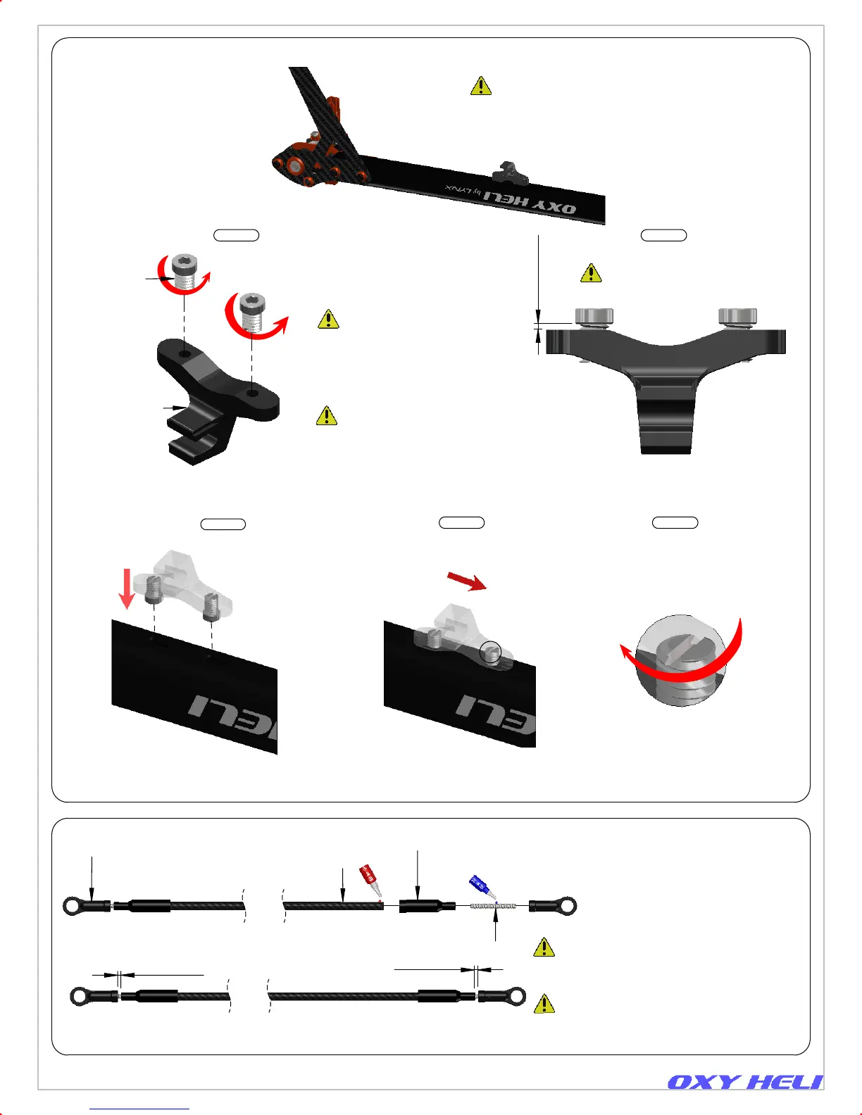
2 x OXY0068
Pin Screw
OXY0067
Guide Push Rod
Note: To install this
pin screw rotate
counter clock wise.
>=0.5mm
A
Main Frame
Push the part inside the
boom sockets as shown.
2 x DR1076
Tail Push Rod Terminal
DR1719
CF Push Rod
2 x OXY0011
4mm-Linkage Ball
2 x OXY0010
Threaded Rod M1.6 X 14
Ref 1mm
Ref 1mm
Page 8
The Plastic ball links have a Lynx logo to give
you information about the turn adjustment,
but have symmetrical ball socket shape
and can be installed in either direction to
achieve the best fine tuning.
Slide the parts as shown.
In order to lock the tail push rod
support, use a Flat Screw Driver
and turn clockwise. Do not
over tighten.
Note Pin Screw Thread:
Oxy designed the Pin Screw with
a counter clockwise thread. This
will help on the final locking
operation. Be careful to follow our
instructions to get a perfect assembly.
Note: Install the Pin Screw and leave
a gap as shown.
Step 1 Step 2
Step 3
Step 4 Step 5
Detail A
Tail Case
Tail Push Rod Guide Assembly.
(CNC components).
Important Note:
The Plastic Terminals and CF Push Rod come
pre assembled with loctite. It is ready to use.
Important Note:
This part comes pre-assembled and
is ready to use. No loctite required.
Carbon Fiber Tail Push Rod Assembly.
(CNC components - Inside Tail Boom)
Chapter 6, Boom Assembly
Instruction Manual Rev 1