MAINTENANCE (cont.)
If the blade (10) angles away from the set square, adjust as follows.
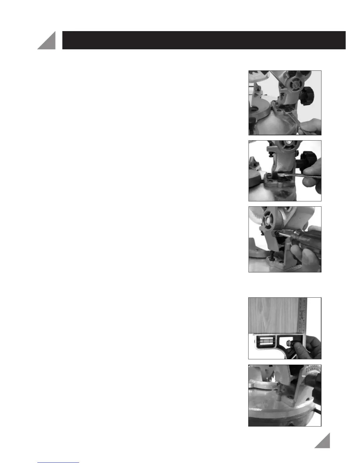
12. Loosen the bevel lock knob (13) by turning in an
anti-clockwise direction.
13. Use a 10mm spanner (not supplied) to loosen the
0° bevel adjustment nut (Fig. 33).
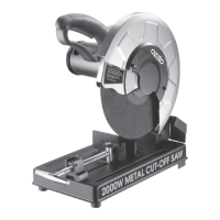
14. To bring the blade into alignment with the set square
adjust the 0° bevel adjustment screw (16) using a
10mm spanner (not supplied) (Fig. 34).
Turning the 10mm spanner in a clockwise direction will
increase the bevel angle (move it above 0°). Turning
the 10mm spanner in an anti-clockwise direction will
decrease the bevel angle (move it below 0°).
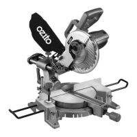
15. Once the blade is aligned with the set square use a
Phillips Head screwdriver (not included) to loosen the
bevel angle indicator (12) (Fig. 35).
16. Using a Phillips Head screwdriver (not included),
loosen the bevel angle indicator (12) by turning in an
anti-clockwise direction (Fig. 35).
17. Adjust the position of the bevel angle indicator (12) so
that it accurately indicates 0° on the bevel scale (14).
18. Re-tighten the bevel lock knob (13) and the 0° bevel
adjustment lock nut (16).
19. Using a scrap piece of wood, perform a straight cut at 0°.
20. Use a set square (not included), to check that the cut is
accurate (Fig. 36).
21. If the cut is not square, repeat steps 1-20 to set the
rotating mitre table (23) square with the blade (10).
NOTE: Using a 45° square the above procedure can also
be used to check the angle of the blade (10) to the
rotating mitre table (23) at a 45° bevel angle. The 45°
bevel adjustment screw (15) is located on the opposite
side to the 0° screw (Fig. 37).
Fig.
33
Fig. 34
Fig. 35
Fig. 36
Fig. 37
18