©2001 PACE Inc., Laurel, Maryland Page 17 of 20
All Rights Reserved
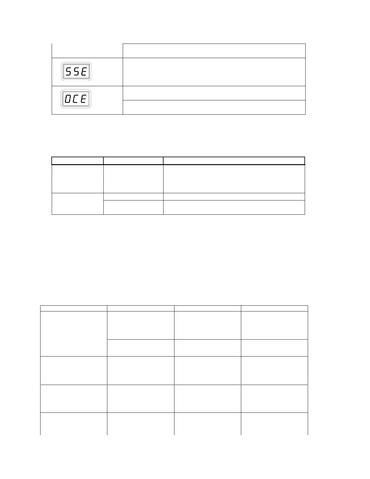
The handpiece heater assembly sensor is open. Refer to table 4
to check handpiece.
The handpiece heater assembly sensor is shorted. Refer to
Table 4 to check handpiece.
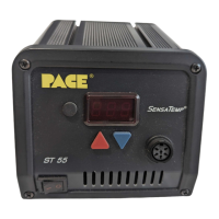
The handpiece heater assembly may be defective. Refer to
Table 4 to check handpiece.
Power source malfunction. Contact PACE or your authorized
local representative for assistance.
Table 2: LED Display Message Codes
Power Source
Most malfunctions are simple and easy to correct. Refer to Table 3.
Symptom Probable Cause Solution
No power to
system
Blown Fuse Check handpiece using table 4. Replace the fuse
(located in the AC Receptacle Fuse Holder) with
one of the same rated value (see Table 6, Spare
Parts)
Defective Heater See Table 4.Handpiece will
not heat
Power Source
Malfunction
Contact PACE
Table 3: Power Source Corrective Maintenance
Handpieces
The following “Heater Assembly Checkout Procedures” (Table 4) is applicable to all PACE
SensaTemp handpieces used with the ST 45 or ST 55 system except for the TT-65 and DTP-80
handpieces. Refer to the applicable manuals for troubleshooting procedures pertinent to these
handpieces.
Perform the procedures with the handpiece heater at room temperature. If the heater is warm,
resistance readings will be different from those shown in Table 4. Disconnect the handpiece from the
power source. Use a meter to check resistance across the handpiece connector plug pins as outlined
in the “Checkout Procedure” column.
System Checkout Procedure Cause Solution
Check resistance: Pin 2 to
Pin 5. Refer to heater
specifications below if
resistance is high, see
Solution
Open Heater Replace Heater AssemblyHandpiece does not heat
Check resistance: Pin 3 to
Pin 6. If circuit reads open,
see Solution
Open Sensor Replace Heater Assembly
Handpiece Overheating Check Resistance: Pin 3 to
Pin 6. Resistance should
be 110 ohms. If resistance
is less than 105 Ohms, see
Solution
Shorted Sensor Replace Heater Assembly
Fuse blows when power
source is turned on
Check resistance: Pin 2 to
Pin 5. Refer to heater
specifications below if
resistance is low, see
Solution
Shorted Heater Replace Heater Assembly
and Fuse
No Ground on Tip Check resistance: Pin 4 to
a new tip. Resistance
should be less than 2 ohms,
if not see Solution
Oxidation build-up in heater
Bore
Clean Heater Bore using
wire brush