System Operations Manual
www.paceworldwide.com
Page 46 of 50
f. Adjust the smaller four screws to bring the platform and PCB level with the vacuum pick.
Loosening a screw will raise that portion of the platform. Tightening a screw will lower
that portion of the platform. To keep the screws tight for every bit you loosen a screw,
tighten the opposite screw equally as much.
g. Once the platform is level, tighten the four large screws.
h. Raise the heater by clicking the red button.
2. Camera alignment. The camera must be aligned to the nozzle on the heater head.
a. Insert a nozzle in the heater head.
b. On the Profile screen, adjust all the heaters to minimum temperatures.
c. Go to the setup screen and click on calibration. Advance to the focus step and click on
the green focus button.
d. Loosen the nozzle retention screw and rotate the nozzle so its 4 sides are aligned with
the edges of the viewing window.
e. Zoom in on the image so it fills the viewing area.
f. If the nozzle edges are too far back:
i. Open the back of the BGA workstation.
WARNING: DO NOT TOUCH LIVE CIRCUITS!
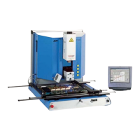
ii. With the camera pulled out, loosen the two screws on the top right of the
camera.
iii. Reposition the camera until the front and back edges are centered in the viewing
window and tighten the screws.
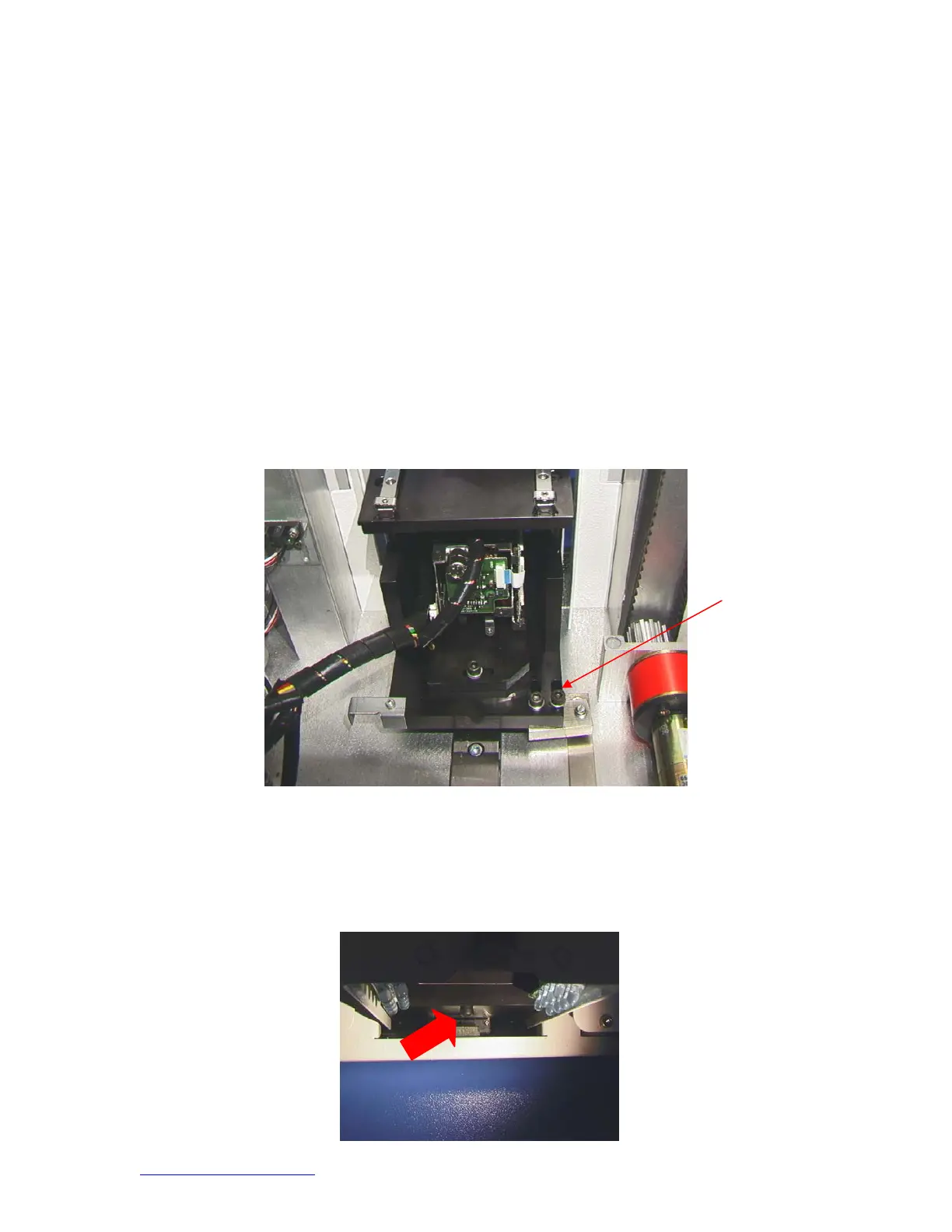
g. If the nozzle edges are off right to left:
i. Open the back of the BGA workstation.
WARNING: DO NOT TOUCH LIVE CIRCUITS!
ii. In front, loosen the screw protruding under the camera housing.