System Operations Manual
www.paceworldwide.com
Page 48 of 50
5. Laser alignment. This adjustment is necessary if, after spotting the PCB with the laser, the
PCB is grossly out of alignment with the nozzle and camera viewing area.
a. Pull out the camera housing.
b. Orient a component on the PCB so it is centered in the viewing area. Make sure the
camera is aligned with the nozzle first. (Step 2)
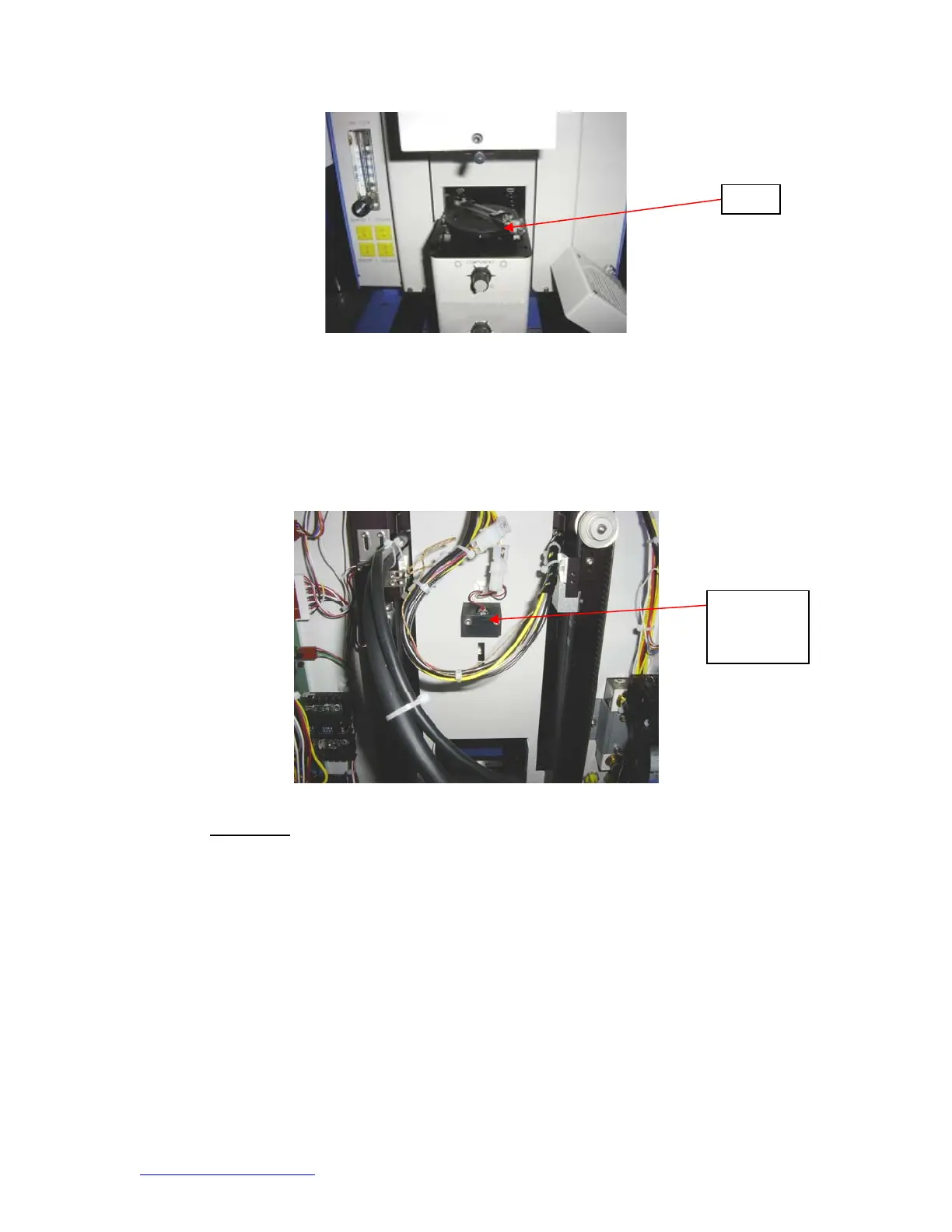
c. Open the back of the BGA workstation. WARNING: DO NOT TOUCH LIVE CIRCUITS!
d. Loosen the two screws holding the laser mount. (Figure)
e. Adjust the laser to a spot roughly in the center of the component and tighten screws.
12. Regulation
a. This product is CE approved.
b. PACE products meet or exceed all applicable military and civilian EOS/ESD,
temperature stability and other specifications, including ANSI-J-STD-001, IPC-
7711, IPC-7721 and IPC-A-610.
es
Laser
adjustment
block